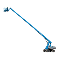
Do you have a question about the Terex Genie S-80 XC Series and is the answer not in the manual?
| Brand | Terex |
|---|---|
| Model | Genie S-80 XC Series |
| Category | Boom Lifts |
| Language | English |
Read and understand safety rules and operating instructions before maintenance.
Information on product accuracy and continuous improvement policies.
Details changes and updates made to the manual over time.
Explains the structure and meaning of machine serial numbers.
Covers essential safety guidelines for operation and maintenance.
Details on tires, wheels, lug nuts, and fluid capacities.
Information on drive speed, braking distance, and boom function speeds.
Covers hydraulic fluid requirements and component specifications.
Details for Deutz, Perkins, and GM engine models.
Provides torque values for machine components and hydraulic fittings.
Guidelines for performing repairs, including safety and preparation.
Procedures for control module, calibration, settings, and software updates.
Covers platform, leveling, rotator, and overload procedures.
Procedures for jib boom, cable track, boom lift, extension, cables, sensors.
Covers RPM adjustment, flex plate, and pump installation.
Procedures for removing and priming function and drive pumps.
Details on manifold components, valve adjustments, and coils.
Procedures for removing and installing fuel and hydraulic tanks.
Covers drive hub, motor, backlash, and tilt sensor procedures.
Procedures for yoke, drive motors, and drive hubs.
Procedure for adjusting hydraulic generator frequency.
Lists and explains fault codes for the machine's control system.
Details fault codes specific to Deutz, Perkins, and GM engines.
Includes symbols, legends, relay layouts, and wiring diagrams.
Includes hydraulic symbols and system diagrams.
Defines symbols used in electrical schematics.
Defines symbols used in hydraulic schematics.
Identifies the location of various limit switches and sensors.
Diagrams for Deutz, Perkins, and GM engine relay configurations.
Lists and describes connector pin assignments for various components.





 Loading...