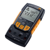
7 Carrying out a measurement
16
7.4. Measuring resistance, capacitance,
continuity and diode test
WARNING
Serious risk of injury to the user and/or destruction of the instrument
during resistance testing.
> Test object must be de-energized.
External voltages will distort the measurement result.
You can use the magnetic suspension system, which is
available as an accessory, order number 0590 0001, to
attach the testo 760 to metal surfaces.
The suspension system’s magnet must not come anywhere
near the battery compartment during the measurement (see
graphic). Automatic adjustment of the measuring range could
be influenced as a result.
Resistors and semiconductors in parallel with the diode will
distort the measurement result.
> Prior to the measurement, make sure that capacitors are discharged.
✓ Instrument is switched on.
7.4.1. testo 760-1
Manual measuring mode
1. Connect test leads: black test lead to the COM jack; red test lead to the
V/Ω/diode/capacitance jack.
- The instrument is in
Ω mode.
2. Switch between resistance, capacitance, continuity and diode test:
press [] <1 s.
- The measured value is shown on the LC display.
7.4.2. testo 760-2/-3
Automatic measuring mode
Automatic detection for resistance/capacitance in the following
range:
• 0.0 ohms to 6.000 mohms
• 0.500 nF to 600.0 µF
Change to manual measuring mode for the remaining measuring
range.
1. Connect test leads: black test lead to the COM jack; red test lead to the
V/Ω/diode/capacitance jack.
- The instrument is in AUTO V mode.
2. Disable AUTO RCDC measuring mode: press [] <1 s.