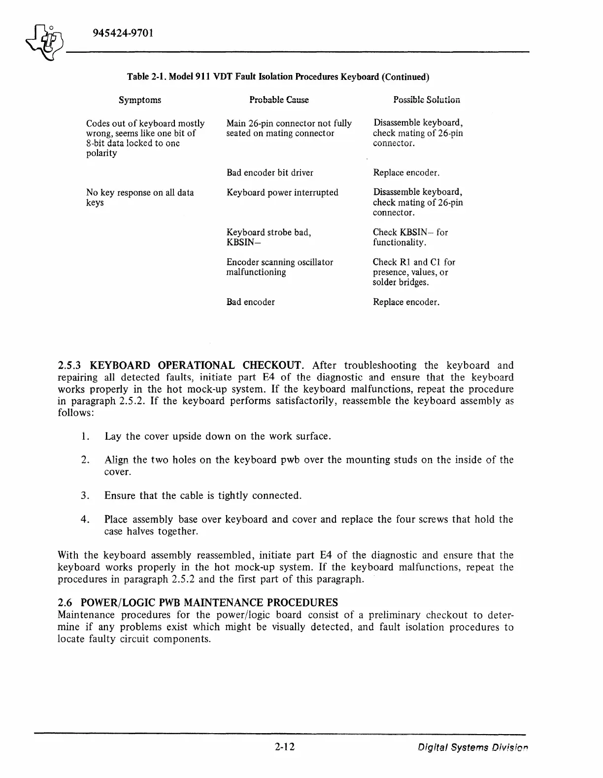
Table 2-1. Model 911 VDT Fault Isolation Procedures Keyboard (Continued)
~umntnmeo
._, J .a••y•vr•••"
Codes
out
of
keyboard mostly
wrong, seems like one bit
of
Q
h-i+
rln+n
1,
..
,,.J,..,.,.,.1
+,....
,....~,.
u-u.u
..
UQ.LQ.
J.V
.....
1'.VU
l.V
Vll\I
polarity
No key response on all data
keys
Probable Cause
Main 26-pin connector
not
fully
seated on mating connector
Bad encoder bit driver
Keyboard power interrupted
Keyboard strobe bad,
KBSIN-
Encoder scanning oscillator
malfunctioning
Bad encoder
Possible Solution
Disassemble keyboard,
check mating
of
26-pin
connector.
Replace encoder.
Disassemble keyboard,
check mating
of
26-pin
connector.
Check
KBSIN-
for
functionality.
Check
Rl
and
Cl
for
presence, values,
or
solder bridges.
Replace encoder.
2.5.3 KEYBOARD OPERATIONAL CHECKOUT.
After
troubleshooting
the
keyboard
and
repairing all
detected
faults, initiate
part
E4
of
the
diagnostic and ensure
that
the
keyboard
works
properly
in
the
hot
mock-up system.
If
the
keyboard
malfunctions, repeat
the
procedure
in paragraph 2.5 .2.
If
the
keyboard
performs satisfactorily, reassemble the
keyboard
assembly
as
follows:
1.
Lay
the
cover upside
down
on
the
work surface.
2. Align
the
two
holes
on
the
keyboard
pwb over
the
mounting
studs
on
the
inside
of
the
cover.
3. Ensure
that
the
cable is tightly
connected.
4. Place assembly base over
keyboard
and
cover and replace
the
four screws
that
hold
the
case halves together.
With
the
keyboard
assembly reassembled, initiate
part
E4
of
the
diagnostic and ensure
that
the
keyboard
works properly in
the
hot
mock-up system.
If
the
keyboard
malfunctions, repeat the
procedures in paragraph 2.5.2 and
the
first
part
of
this paragraph.
2.6
POWER/LOGIC
PWB
MAINTENANCE PROCEDURES
Maintenance procedures for the power/logic board consist
of
a preliminary
checkout
to
deter-
mine
if
any problems exist which might be visually
detected,
and fault isolation procedures
to
locate faulty circuit components.
2-12
o;gital
Systems
Division