~~-------
~
945424-9701
VDT
CONTROLLER
l
(A)136254
(
/~
MODS
ELA-
I'"
1
48Ml--~~~~~~~~~~~~~---s,48I
CRUBIT12
:
::r
CRUBIT13
1
3
-
36
-
2
r
CRUBIT14
~A ~~
--r
CRUBIT1
5 I
p 2
3414
34
CRUBiTOUT
18
22
14
60
"66
......
.,,,,
r:s
P 1 I
166
l,
.....
i...
-....-
i....
STORECLK-
~
l.L
TLIORES-
r-
CRUBITINT
NKBINT
MODSELB-
i...
....
NKBINT
*
.
NOTE.
INTERFACE
IMPLEMENTED
BY
INSERTING
VDT
CONTROLLER
.....
--
.....
--
......
...
INTO
COMPUTER
BACKPANEL
SLOT
18
22
14
60
•
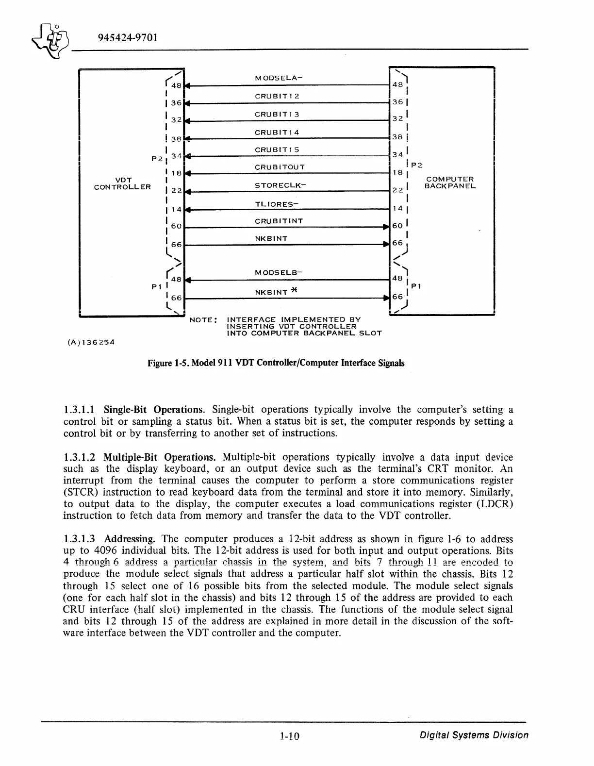
Figure 1-5. Model 911 VDT Controller/Computer Interlace Signals
P2
COMPUTER
BACK
PANEL
1.3.1.1 Single-Bit Operations. Single-bit operations typically involve the computer's setting a
control bit
or
sampling a status bit. When a status bit
is
set, the computer responds by setting a
control
bit
or
by transferring
to
another set
of
instructions.
1.3.1.2 Multiple-Bit Operations. Multiple-bit operations typically involve a data
input
device
such
as
the display keyboard,
or
an
output
device such
as
the terminal's CRT monitor. An
interrupt from the terminal causes the computer
to
perform a store communications register
(STCR) instruction
to
read keyboard data from the terminal and store
it
into memory. Similarly,
to
output
data
to
the display, the computer executes a load communications register (LDCR)
instruction
to
fetch data from memory and transfer the data
to
the VDT controller.
1.3.1.3 Addressing. The computer produces a 12-bit address
as
shown in figure
1-6
to
address
up
to
4096 individual bits. The 12-bit address is used for
both
input
and
output
operations. Bits
4 throrn:Yh
fl
::iililrP.~~
::i
n::irtir.111::ir
r.h::i~~i~
in
thP.
~v~tP.m
::inil
hit~
7
thrrnwh
11
::irP
Pnrr1ilPrt
tr1
w
------~er-
-
-------
-
r------~---
--------- --- ---- -.1----
.....
,
---
___
..,,,
. ------
...
a--
--
---
_
......
_____
--
produce the module select signals
that
address a particular
half
slot within the chassis. Bits 12
through
15
select one
of
16 possible bits from
the
selected module. The module select signals
(one for each half slot in the chassis) and bits 12 through
15
of
the
address are provided
to
each
CRU interface (half slot) implemented in the chassis. The functions
of
the module select signal
and bits 12 through
15
of
the address are explained in more detail in the discussion
of
the soft-
ware interface between the VDT controller and the computer.
1-10
Digital
Systems
Division