J}J~
______
_
~
945424-9701
FROM
POWER/
LOGIC
PWB
(A)
1
36280
VIDEO
----
BRIGHTNESS
CIRCUITRY
VIDEO
AMP
VIDEO
FLYBACK
HI-VOLTAGE
CIRCUITS
HORI-
HORIZONTAL
ZONTAL
-+--------------DEFLECTION
SYNC
VERTICAL
VERTICAL
SYNC
-+------------..
DEFLECTION
I
I
I
I
L
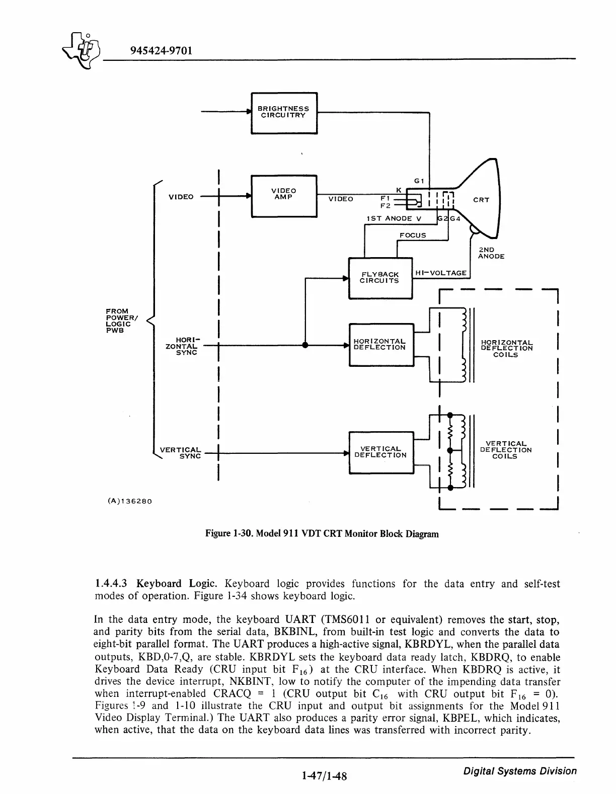
Figure 1-30. Model 911 VDT CRT Monitor Block Diagram
2ND
ANODE
HORIZONTAL
DEFLECTION
COILS
VERTICAL
DEFLECTION
COILS
--,
I
I
I
I
I
I
I
I
_
_J
1.4.4.3 Keyboard Logic. Keyboard logic provides functions for the data
entry
and self-test
modes
of
operation. Figure 1-34 shows keyboard logic.
In the data
entry
mode, the keyboard UART (TMS6011
or
equivalent) removes the start, stop,
and parity bits from the serial data, BKBINL, from built-in test logic and converts
the
data
to
eight-bit parallel format. The UART produces a high-active signal, KBRDYL, when the parallel
data
outputs, KBD,0-7 ,Q, are stable. KBRDYL sets the keyboard data ready latch, KBDRQ,
to
enable
Keyboard Data Ready (CRU input bit F
16
)
at
the CRU interface. When KBDRQ
is
active,
it
drives the device interrupt, NKBINT, low
to
notify the
computer
of
the impending
data
transfer
when interrupt-enabled CRACQ = 1 (CRU
output
bit C
16
with CRU
output
bit F
16
= 0).
Figures l-9 and 1-10 illustrate the CRU input and
output
bit assignments for the Model 911
Video Display Terminal.) The UART also produces a parity error signal, KBPEL, which indicates,
when active,
that
the data on the keyboard data lines was transferred with incorrect parity.
1-47 /1-48
Digital
Systems Division