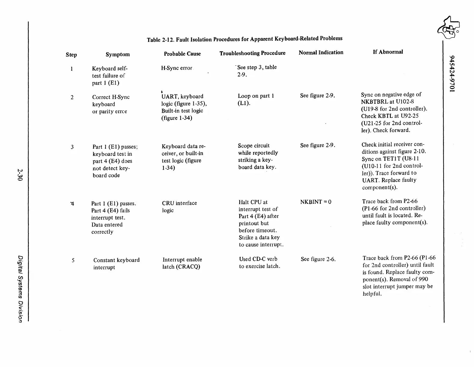
Table 2-12. Fault Isolation Procedures for Apparent Keyboard-Related Problems
~
Step
Symptom
Probable Cause
Troubleshooting
Proced1L1re
Normal Indication
If
Abnormal
"°
~
Keyboard self-
H-Sync error
-See step
3,
table
Vt
~
test failure
of
2-9.
N
~
I
part 1
(El)
"°
......
0
•
,,_
2
Correct H-Sync
UART, keyboard
Loop
on
part 1
See figure 2-9.
Sync
on
negative edge
of
keyboard
logic (figure 1-35),
(LI).
NKBTBRL at
Ul
02-8
or parity error
Built-in test logic
(U19-8 for 2nd controller).
(figure 1-34)
Check KBTL at U92·25
(U21-25 for 2nd control-
ler). Check forward.
3
Part 1
(El)
passes;
Keyboard data re-
Scope circuit
See figure 2-9.
Check initial receiver con-
keyboard test in
ceiver, or built-in
while reportedly
ditions
aga•inst
figure 2-10.
part 4 (E4) does
test logic (figure
striking a key-
Sync on TETI T (U8- l l
t-.J
not
detect key-
1-34)
board data key.
(UI0-11 for 2nd control-
w
board code
ler)). Trace forward
to
0
UART. Replace faulty
component(s).
Part 1 (E 1) passes.
CRU interface
Halt CPU at
NKBINT =O
Trace back from P2-66
Part 4 (E4) fails
logic
interrupt test
of
(Pl-66
for 2nd controller)
interrupt test.
Part 4 (E4) after
until fault
is
located.
Re-
Data entered
printout but
place faulty componcnt(s).
correctly
before timeout.
Strike a data key
to
cause interrupt.
t:J
5
Constant keyboard
Interrupt enable
Used
CD-C
verb
See figure 2-6.
Trace back from P2-66 (P 1-66
<§~
.....
interrupt
latch (CRACQ)
to exercise latch.
for 2nd controller) until fault
~.
is
found. Replace faulty com-
(/)
'<
ponent(s). Removal
of
990
(I)
......
slot interrupt jumper may
be
CD
3
CIJ
helpfuL
0
<;•
~·
a·
::>