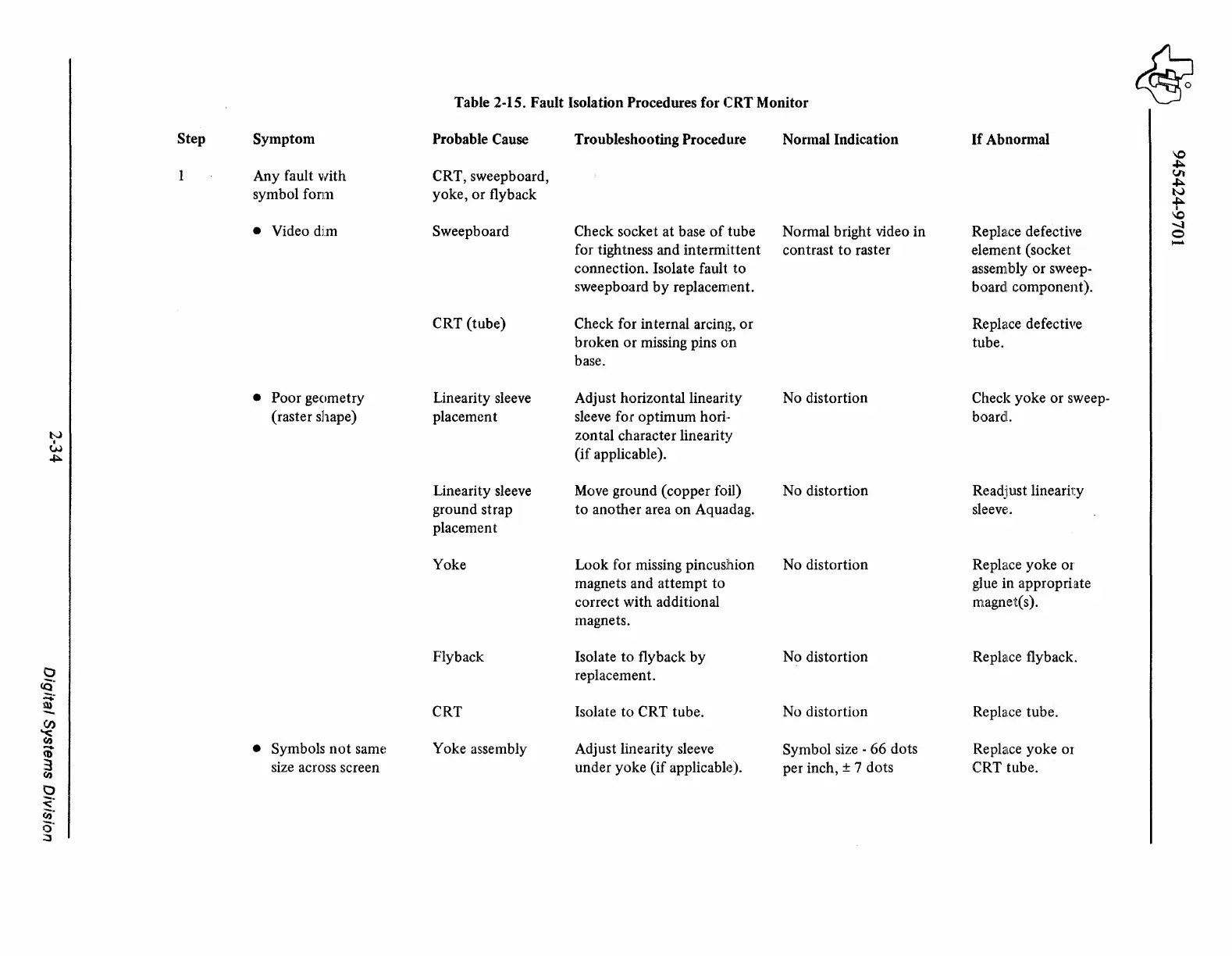
Table 2-15. Fault Isolation Procedures for CRTMonitor
~
Step
Symptom
Probable Cause Troubleshooting Procedure
Normal Indication
If
Abnormal
\0
+:-.
Any fault with
CRT, sweepboard,
Vt
+:-.
symbol form
yoke, or flyback
N
+:-.
I
\0
• Video dim
Sweepboard Check socket at base
of
tube
Normal bright video in Replace defective
-..J
0
for tightness and intermittent
contrast
to
raster
eleme:nt (socket
-
connection. Isolate fault
to
assembly or sweep-
sweepboard
by
replacement.
board!
component).
CRT (tube)
Check for internal arcing,
or
Rephtce defective
broken or missing pins
on
tube.
base.
• Poor geometry
Linearity sleeve Adjust horizontal linearity
No distortion
Check yoke or sweep-
(raster shape) placement sleeve for optimum hofi.·
board!.
t-..>
zontal character linearity
w
(if
applicable).
~
Linearity sleeve
Move
ground (copper foil) No distortion Readjust linearii:y
ground strap
to
another area on Aqua.dag.
sleeve:.
placement
Yoke Look for missing pincushion No distortion Replace yoke or
magnets and attempt
to
glue in appropriate
correct with additional
magnet(s).
magnets.
Fly back Isolate
to
flyback by No distortion
Replace flyback.
0
replacement.
<9:
~
CRT
(J)
Isolate
to
CRT tube. No distortion
Replalce
tube.
"<
(I)
Symbols
not
sam~:
Yoke assembly Adjust linearity sleeve
Symbol size - 66 dots
Replalce
yoke
01
(i)
•
3
size across screen under yoke
(if
applicable~).
per inch, ± 7 dots CRT tube.
(I)
0
<·
rn·
a·
~