~-----~~~~~~~-----------~~~
~
945424-9701
,-
- - - - - - - - - - - - -
--
- -
VERTICAL
Q302
VERT.
D12
VIDEO
DISPLAY 15.7KHz
Q308
VERT.
+C401
'=?'4714'"
...L
SOV
I
osc. I I
R320
221<
t~
R306
47
2SV
R305
391(
RETRACE
CONTROL
®
l~.
R402
IK
__JJ
Q301
VERT.
OSC. I
C302
T-15
...LC314
9.IK
r--
R303
22i<
~
Q303
VERT.
l\MP.
I
~CR304
Q307
VERT.
R321
75
R322
+C402
T4.7MF
_l
63V
R403
IK
R418
~'SKl
Q402
VIDEO
DRIVER
J.0047
R314
I.BK
OUT.
I I
C309
1014'"
2SV
1
R408
47
CR102
RI03
9.2K
"2%
CJIJ
R312
I+
.. I
I
!MF•
25\IR31315K
t•-C-305 _
_,,,j~""'
--t~307
_l..4,7MF
IMF
16V
2SV
I
R316 I
75
o C312
T
+IOOOMF
16V
R325
C311
R323
T.022
820
t------J
!:~24
I
I
~----------+-----...------~~---..----f'H-O_R_I_z_o_~J_T_A_L-.----..----r~..,,.~~-c~:....;"
·100
.!'.o,~
f
RI02
8.2K
•2r.
~02
I
1s~
;L~
RIOS
8.2K
C104 ;
Rl09
~~~
R106
S6K
CllO
Rll2
6.BK
;02r.
CllS
I CIOS
n2P~~
-fr---+---a:
RI
11
I
16
~
IOK
"'2r.
METllL
1
Rll3
A
267K/
'\_
"17.
Rll4
267K
•tr.
+C109
T
4.7MF
25V
L.-.:..._:_.
1~
. .J I
I
Rll7
r-t------1~---~3.~
~
T!Ol~
;\
1
•
Ql05
r11qJ·,,,
"27. -
HORIZ.
__J
=
QlOl
HORIZ.
DSC. I
TIO~F----+l'I_
!+----+~
cR101
METl\L.
L
H~
1
R
0
?z.
I
Clll
FILM
DSC.
Ill
DR/l.....,V~ER_____
.
Lui
rOl
~l
ssh
i
RllO
CR103
I
~560
1§~1
4
R412
!OOK
R414
BRIGHTNESS
_[10
MEG
= •s::
1/2H
416
I R417
~L-!
I 82K R415
68()1(
2
MEG.
FOCUS
C404
1.02
I
Rllll
i
c\~
~~z:
sO:JcVE
=
L _ -
---
±.
-
---3~
-
---
- -
---
- -
----
- -
----
- -
----
- -
---
- -
---
- -
---
- -
---
- -
---
i--------------------------,
P.C.
801\RD
EDGE
CONNECTOR
KEY
CFOIL
SIDEl
@000©®©®00
0 =
DC
VOL
Tl\GE
SOJRCE
0 =
DC
VOL
Tl\GE APPLIED
NOTE: I.
CUSTOMER
SUPPLIED EXTERNAL 0 C
SOURCE
ON
PIN
7
EDGE
CONNECTOR
IMPORTANT:SAFETY
NOTICE.
When
aervlc1nG
thl~
chassis,
uncter
no
clreumstances
sh~uld
the
orlgl-
rial
dellgn be
modtffed
or
altered
wlthoUt
permtaslon
from
the Zenith
Radio
C<>rporatlon.
All components
should
be
replaced
only
with
types
ldenttcal
to
those
In
the
orlQfnal
circuit. Special
components
are
used
to prevent shock
and
fire hazard.
These
critical
components
are
shad-
ed
on
the schematic and
parts
list for
easy
Identification.
Thia circuit diagram may occasionally differ from the actual circuit
used.
This
way,
Implementation of the latest safety and
performance
lmprovtment
changes
Into the set ls not delayed until the
new
MrYlce
literature
18
printed.
YEL/GRN
BLU
R205
=-I
I
47K.
"'10%
l/2H
E204
I
C201
oi
9
J.01
~
R204
C405
J.01
I 1()1(.
*1or.
I I
l/2H
1E203
I
I L
__
_:_
__
J
IMP<>AT
ANT
SAF&n
NOTlCE
Pb~
'X;RADb\TfoN~·
·FIRE
.
OR·,
SHOCK
HAZARD
PREV,ENTION,1
CERTAIN
SPE·
CIAL
OR
REDUNDANT
PARTS.ARE
USED.
USE
I
ONL
V'
EXACT
REPLACDIENTS.
·DO
NOT
Al.TEA
THE
CIRCUIT
OR
DEFEAT
THE
FUSES.
FAILURE
TO
COMPL
V
MAY
BE
UNLAWFUL.
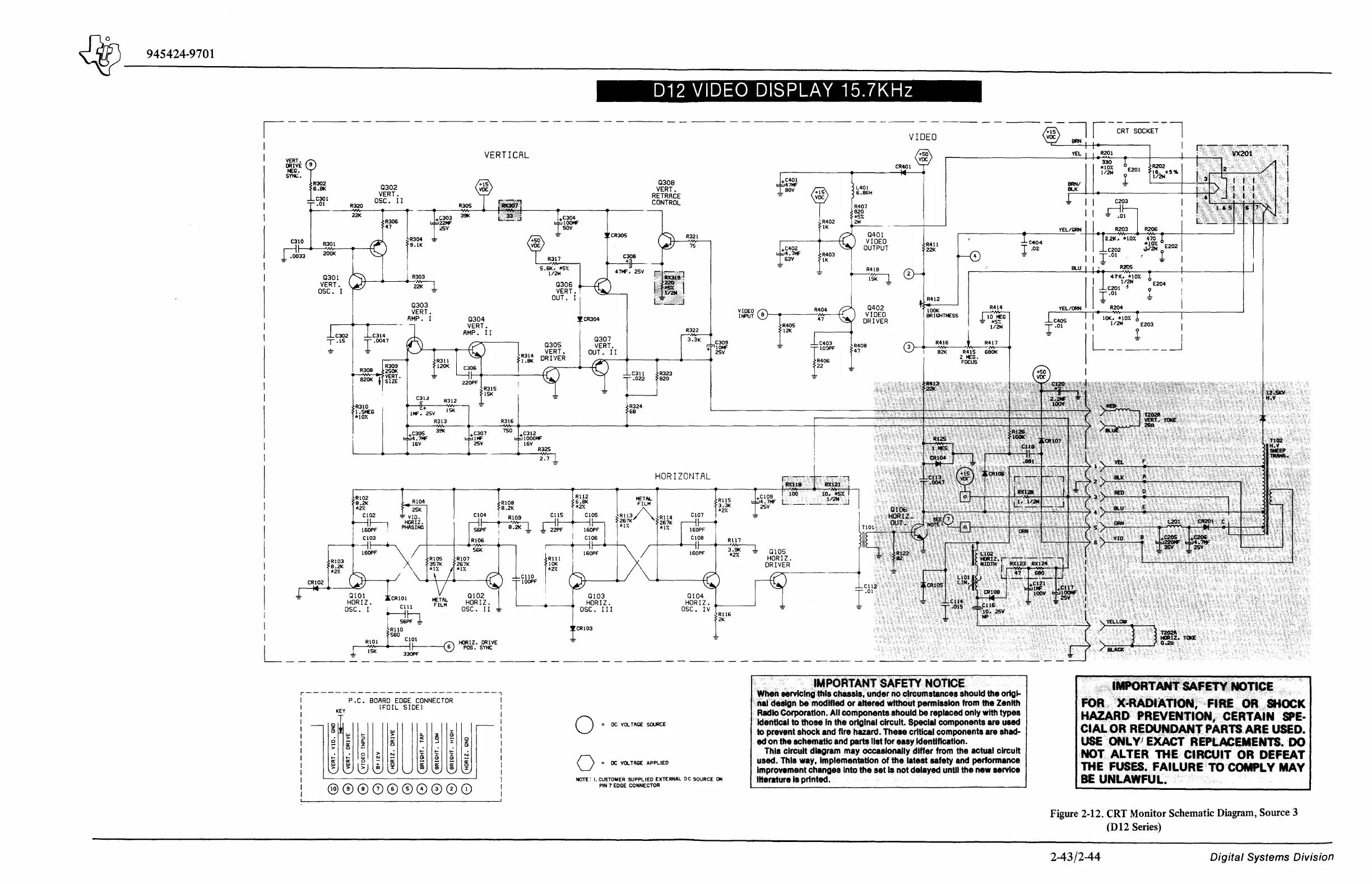
Figure 2-12. CRT Monitor Schematic Diagram, Source 3
(D12 Series)
2-43/2-44
Digital
Systems Division