Computer
USB I2C
EV2400
Power
Supply
or Cells
+
-
Load
bq34110EVM Quick Start Guide
www.ti.com
4
SLUUBI1A–October 2016–Revised July 2018
Submit Documentation Feedback
Copyright © 2016–2018, Texas Instruments Incorporated
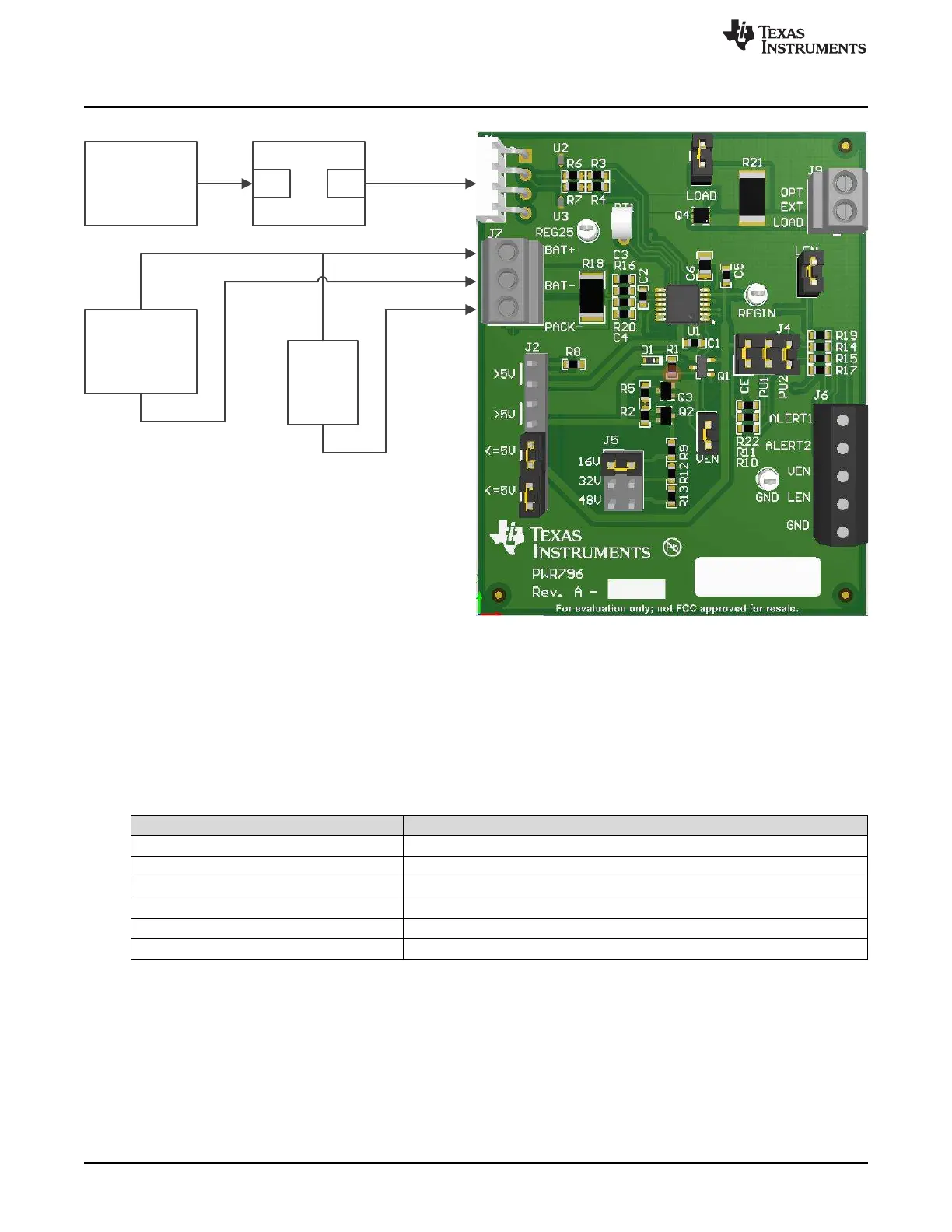
bq34110EVM-796 Evaluation Module
Figure 1. bq34110 Circuit Module Connection to Pack and System Load
2.5.2 Circuit Module Connections
Contacts on the circuit module provide the following connections:
• Direct connection to the battery pack (J7): BAT+ and BAT–
See Table 3 to configure J2 and J5 to support the voltage range for your pack.
Table 3. Cell Configuration Jumper Placement
Cell Configuration Jumper Placement
J2:
Single cell or stack voltage less than 5 V Place jumpers in the ≤ 5-V positions
Multicell: Place jumpers in the > 5 V positions
J5:
Single cell: Does not matter
Multicell: Place the jumper to the appropriate setting for your series cell configuration
Attach BAT– to the bottom of the battery stack and attach BAT+ to the top of the battery stack.
• Charger or load connection (J7): BAT+ and PACK–
Attach the load or power supply to the J7 terminal block. Connect the positive load or power supply
wire to the terminal block position labeled BAT+. Connect the ground wire for the load or power supply
to the terminal block position labeled PACK–.

 Loading...


