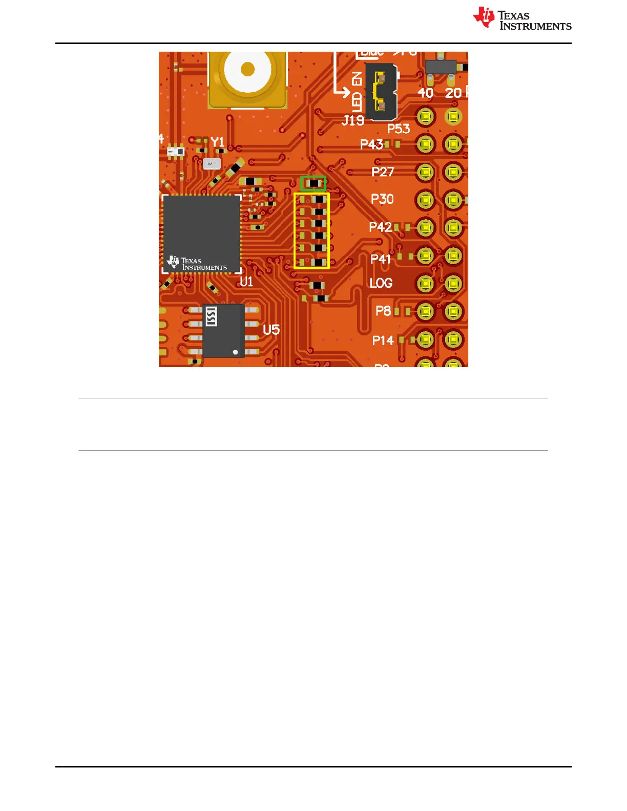
Figure 2-9. SD Slot Resistor Change
Note
Conventional SD memory cards normally require 3.3V interface. Verify that the corresponding VIO ring
for these SDMMC lines (VIO1) from the CC35xx is set to 3.3V using the appropriate VIO jumper. For
details on this jumper, see Section 2.2.1.
2.1.5 External Memory Interface
The CC35xxE requires xSPI external flash memory for execution code, and supports adding optional external
PSRAM on the same xSPI bus for additional runtime memory. The LP-EM-CC35X1 features an onboard external
flash (U5) and a footprint for assembling an additional PSRAM (U6).
To use external PSRAM on the LP-EM-CC35X1, users must perform the following hardware changes:
• Solder APS1604M-SQRX-SN PSRAM on the footprint U6.
• R27 footprint on the front of the board must be populated with a 0 ohm resistor (0201).
• R55 footprint on the front of the board must be populated with a 0 ohm resistor (0402).
• R56-R60 footprints on the back of the board must be populated with 0 ohm resistors (0201).
Hardware www.ti.com
10 CC35xxE LaunchPad™ Development Kit for SimpleLink™ Wi-Fi 6 and
Bluetooth® Low Energy Wireless MCU
SWRU629 – SEPTEMBER 2024
Submit Document Feedback
Copyright © 2024 Texas Instruments Incorporated