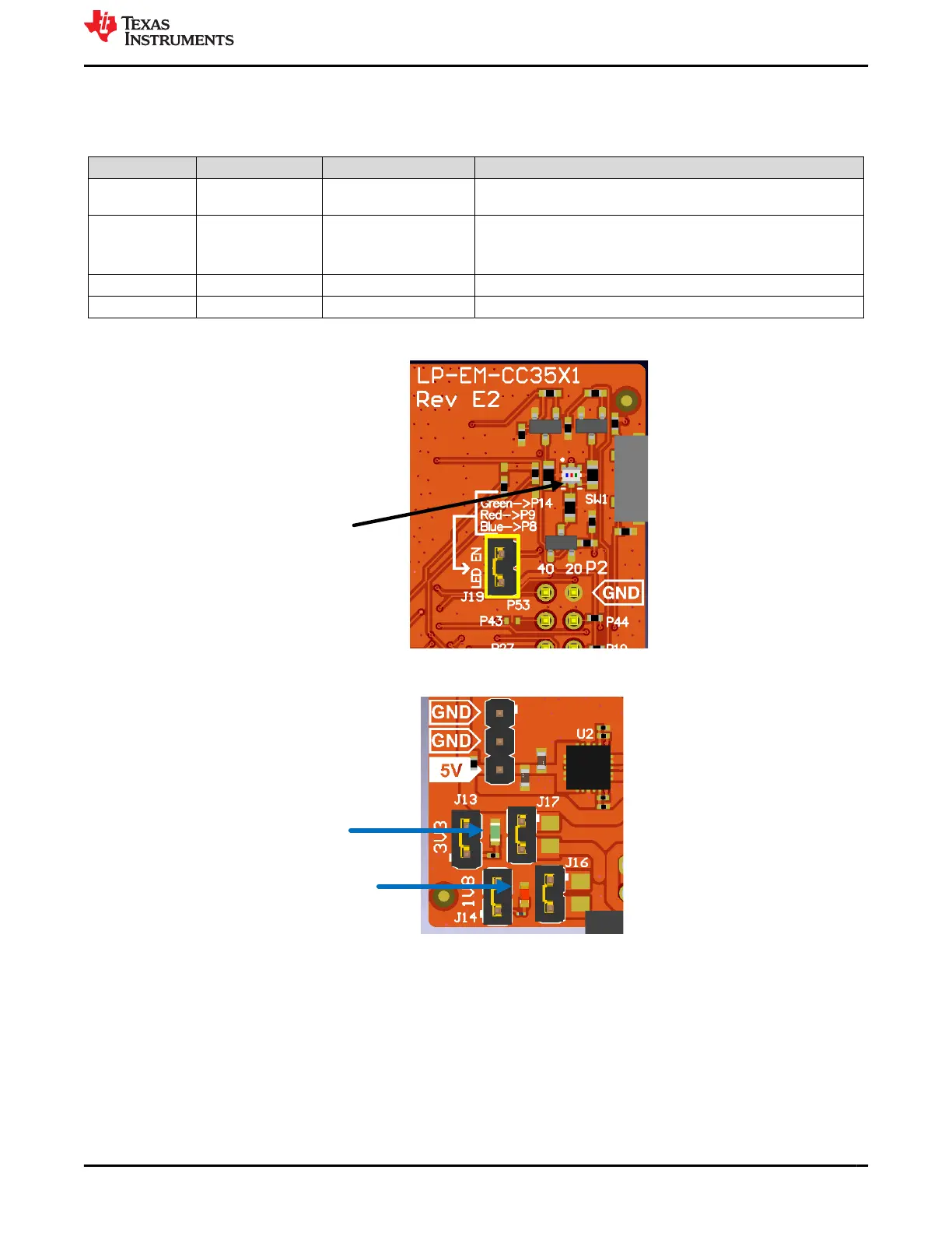
2.1.9 LED Indicators
The LED indicators are listed in Table 2-7.
Table 2-7. LED Indicators
Reference Color Use Comments
D2 Yellow nRESET Indicates the state of the nRESET pin. If this LED is on, the device is
functional.
D4 RGB Green - GPIO30
Red - GPIO34
Blue - GPO35
On when the GPIOx is logic-1.
(1)
D9 Green 3.3V power indication On: 3.3V power rail is up. Off: no 3.3V power supplied.
D10 Red 1.8V power indication On: 1.8V power rail is up. Off: no 1.8V power supplied
(1) The RGB LEDs can be disconnected from the power supply by removing jumper J19 (LED EN). This can be used when measuring
current to the CC35xxE.
Figure 2-17. RGB LEDs
Figure 2-18. Power LEDs
www.ti.com Hardware
SWRU629 – SEPTEMBER 2024
Submit Document Feedback
CC35xxE LaunchPad™ Development Kit for SimpleLink™ Wi-Fi 6 and
Bluetooth® Low Energy Wireless MCU
15
Copyright © 2024 Texas Instruments Incorporated