2.1.10 LaunchPad
™
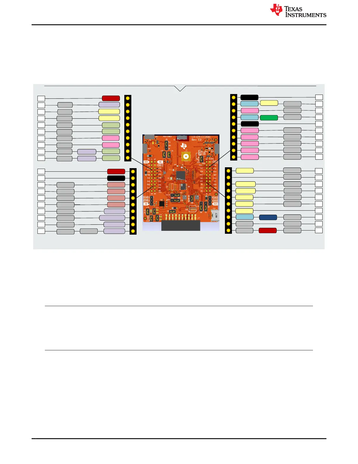
Header Pin Assignment
The LP-EM-CC35X1 features 2 x 20 pin connectors that provide access to many of the CC35xxE pins and
features. The LaunchPad header pinout is standard in TI, allowing easy stacking of other TI BoosterPacks on the
LP-EM-CC35xx for quick interface with peripheral boards.
The CC35xxE LaunchPad follows this standard. For CC35xxE pin-mapping assignments and functions, see
Figure 2-19.
GPIO18
GPIO0
3V3
UART0_RX
UART0_TX
GPIO17
SPI0_CLK
GPIO27
1
2*
3
4
5
6
7
8
9
10
GPIO6
5V
GPIO5
ADC5
I2S WCLK
GPIO26
GPIO29
GPIO30
GPIO35
I2S Data0
I2S Data1
21
22
23
24
25
26
27*
28*
29*
30*
GPIO26
GPIO2
GND
GPIO30
SPI0 POCI
GPIO28
GPIO13
20
19
18
17
16*
15
14
13
12
11
SPI0 CS
RESET
SPI0 PICO
GPIO29
GPIO15
GPIO12
GPIO19
GPIO16
GPIO35
40
39*
38
37
36*
35*
34
33*
32*
31
GPIO6
GPIO34
GPIO30
DCAN TX
Logger
UART1 TX
GPIO5
GND
ADC2
ADC3
ADC4
GPIO4
GPIO3
I2S MCLK/BCLK
I2C1 Data
I2C1 CLK
GPIO10
GPIO11
SPI1_CLK
GPIO14
I2C0 CLK
I2C0 Data
PDM Data0
PDM BCLK
GPIO33
GPIO32
SPI1 PICO
SPI1 CS
SPI1 POCI
GPT1_1
GPIO31
DCAN RX
SLOW_CLK_IN
UART1 RX
GPT0_1
UART0 RTS
UART0 CTS
GPIO4
GPIO36
*These pins are not connected to the Launchpad Connector by default
RED LED
GRN LED
SW2
GPT1_3
SW1
BLUE LED
Figure 2-19. CC35xxE LaunchPad Header Pin Assignments
All the signals are referred to by the GPIOx in the SDK. The default mappings are shown in Figure 2-19. Some
of the pins are repeated across the connector. For example, GPIO4 is available on header pin 25 and pin 39,
but only pin 25 is connected by default. The signal on LaunchPad header pin 39 is marked with an asterisk (*) to
signify that the signal is not connected by default. The signal can be routed to the pin by using a 0Ω resistor in
the path.
Note
The LP-EM-CC35X1 has two jumpers, which can control the voltage of VIO1 and VIO2. The jumpers
provide reference voltage for the various CC3551E IOs, and can be configured to 3.3V or 1.8V. When
using the GPIOs connected to the LaunchPad header pins, knowing what VIO the jumpers correspond
to, and how to configure them to be either 3.3V or 1.8V is important. For more information, refer to
Section 2.2.1.
Hardware www.ti.com
16 CC35xxE LaunchPad™ Development Kit for SimpleLink™ Wi-Fi 6 and
Bluetooth® Low Energy Wireless MCU
SWRU629 – SEPTEMBER 2024
Submit Document Feedback
Copyright © 2024 Texas Instruments Incorporated