2.1.6 ADC Interface
The CC35xxE features a 12-bit ADC with 8 channels. The LP-EM-CC35X1 enables use of 4 ADC channels
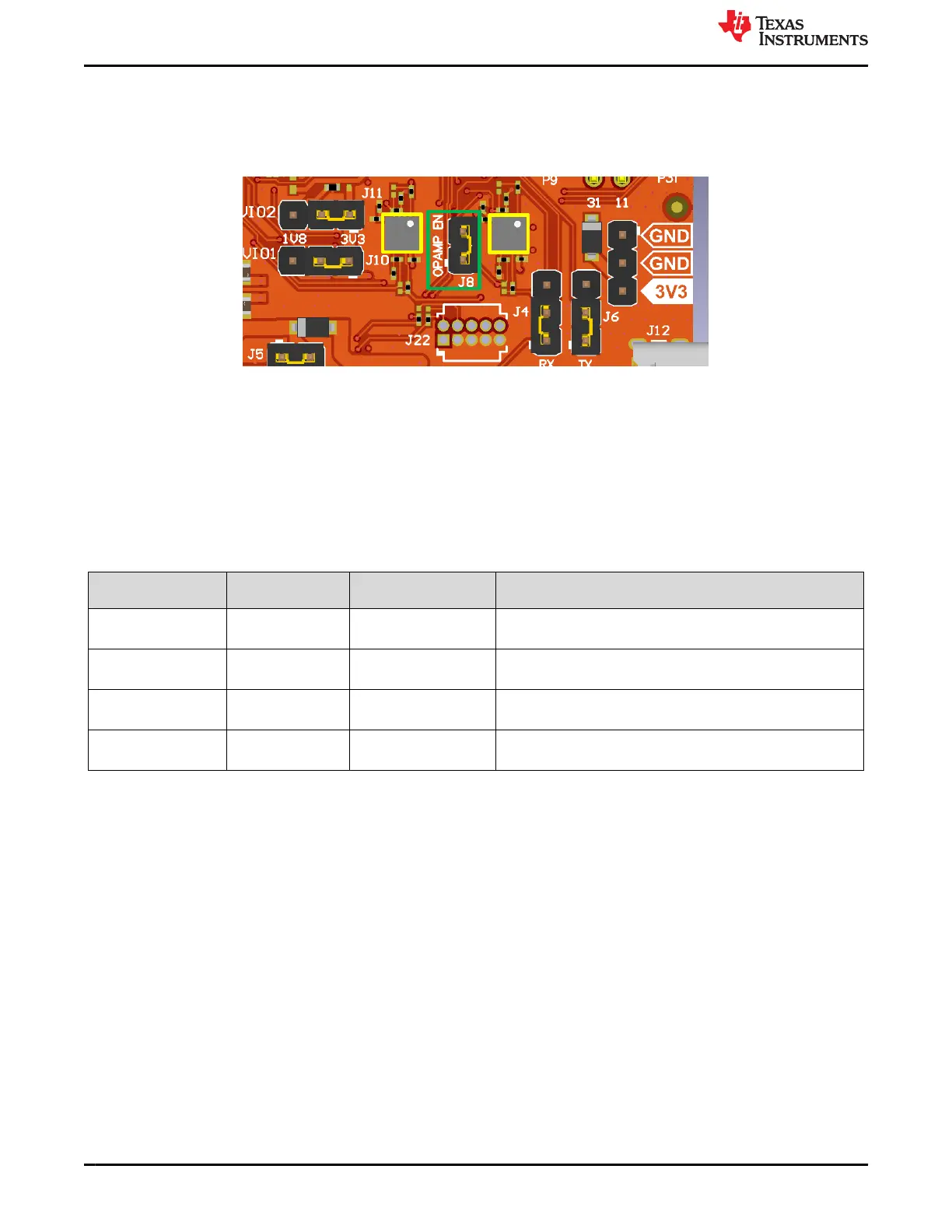
with onboard buffers for impedance controlling. The two OPA2211 dual channel operational amplifiers (U7, U10),
which are configured as impedance buffers for four ADC channels can be seen in Figure 2-12.
Figure 2-12. ADC Buffers
The four ADC channels which are available on the LP-EM-CC35X1 are ADC2, ADC3, ADC4, and ADC5. A
jumper is also provided to disconnect the power to U7 and U10 for current measurements of the CC35xx.
If users want to use the corresponding GPIOs which are used as the ADC channels without the buffers, then
there is the possibility to route around the buffers by removing and placing certain 0 ohm resistors.
The GPIO configuration of the ADC channels and which resistors need to be changed for buffer reroute can be
seen in Table 2-5.
Table 2-5. ADC GPIO Configuration
ADC Channel GPIO # (CC35xx)
LaunchPad Header Pin
#
Needed Configuration For Unbuffered GPIO Use
ADC2 GPIO6 23 remove: R44, R52
place: R71
ADC3 GPIO5 24 remove: R73, R75
place: R79
ADC4 GPIO4 25 remove: R41, R50
place: R70
ADC5 GPIO3 26 remove: R72, R74
place: R78
The locations of the resistors mentioned in Table 2-5 can be seen in Figure 2-13.
As an example, if users want to use GPIO4 unbuffered, which is connected to LaunchPad header pin 26 on the
LP-EM-CC35X1, then the following resistors need to be changed:
• Remove R41 and R50
• Place 0 ohm resistor (0201) R70
Hardware www.ti.com
12 CC35xxE LaunchPad™ Development Kit for SimpleLink™ Wi-Fi 6 and
Bluetooth® Low Energy Wireless MCU
SWRU629 – SEPTEMBER 2024
Submit Document Feedback
Copyright © 2024 Texas Instruments Incorporated