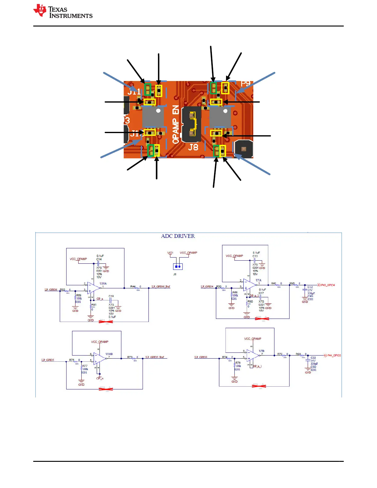
R52:
remove for
reroute
R44:
remove for
reroute
R71:
place for
reroute
R79:
place for
reroute
R73:
place for
reroute
R75:
remove for
reroute
GPIO 6
GPIO 5
R50:
remove for
reroute
R41:
remove for
reroute
R70:
place for
reroute
GPIO 4
R74:
remove for
reroute
R72:
remove for
reroute
R78:
place for
reroute
GPIO 3
Figure 2-13. ADC Buffer Reroute Configuration
The area of the LP-EM-CC35X1 schematic which encompasses the ADC buffers is shown in Figure 2-14.
Figure 2-14. ADC Buffers Schematic
www.ti.com Hardware
SWRU629 – SEPTEMBER 2024
Submit Document Feedback
CC35xxE LaunchPad™ Development Kit for SimpleLink™ Wi-Fi 6 and
Bluetooth® Low Energy Wireless MCU
13
Copyright © 2024 Texas Instruments Incorporated