DRV8833
www.ti.com
SLVSAR1E –JANUARY 2011–REVISED JULY 2015
8.2.2.2 Motor Current Trip Point
When the voltage on pin xISEN exceeds V
TRIP
(0.2 V), current regulation is activated. The R
ISENSE
resistor should
be sized to set the desired I
CHOP
level.
R
ISENSE
= 0.2 V / I
CHOP
(2)
To set I
CHOP
to 1 A, R
SENSE
= 0.2 V / 1 A = 0.2 Ω.
8.2.2.3 Sense Resistor
For optimal performance, it is important for the sense resistor to be:
• Surface-mount
• Low inductance
• Rated for high enough power
• Placed closely to the motor driver
The power dissipated by the sense resistor equals I
RMS
2
× R. For example, if peak motor current is 3 A, RMS
motor current is 2 A, and a 0.05-Ω sense resistor is used, the resistor will dissipate 2 A
2
× 0.05 Ω = 0.2 W. The
power quickly increases with higher current levels.
Resistors typically have a rated power within some ambient temperature range, along with a derated power curve
for high ambient temperatures. When a PCB is shared with other components generating heat, margin should be
added. For best practice, measure the actual sense resistor temperature in a final system, along with the power
MOSFETs, as those are often the hottest components.
Because power resistors are larger and more expensive than standard resistors, the common practice is to use
multiple standard resistors in parallel, between the sense node and ground. This distributes the current and heat
dissipation.
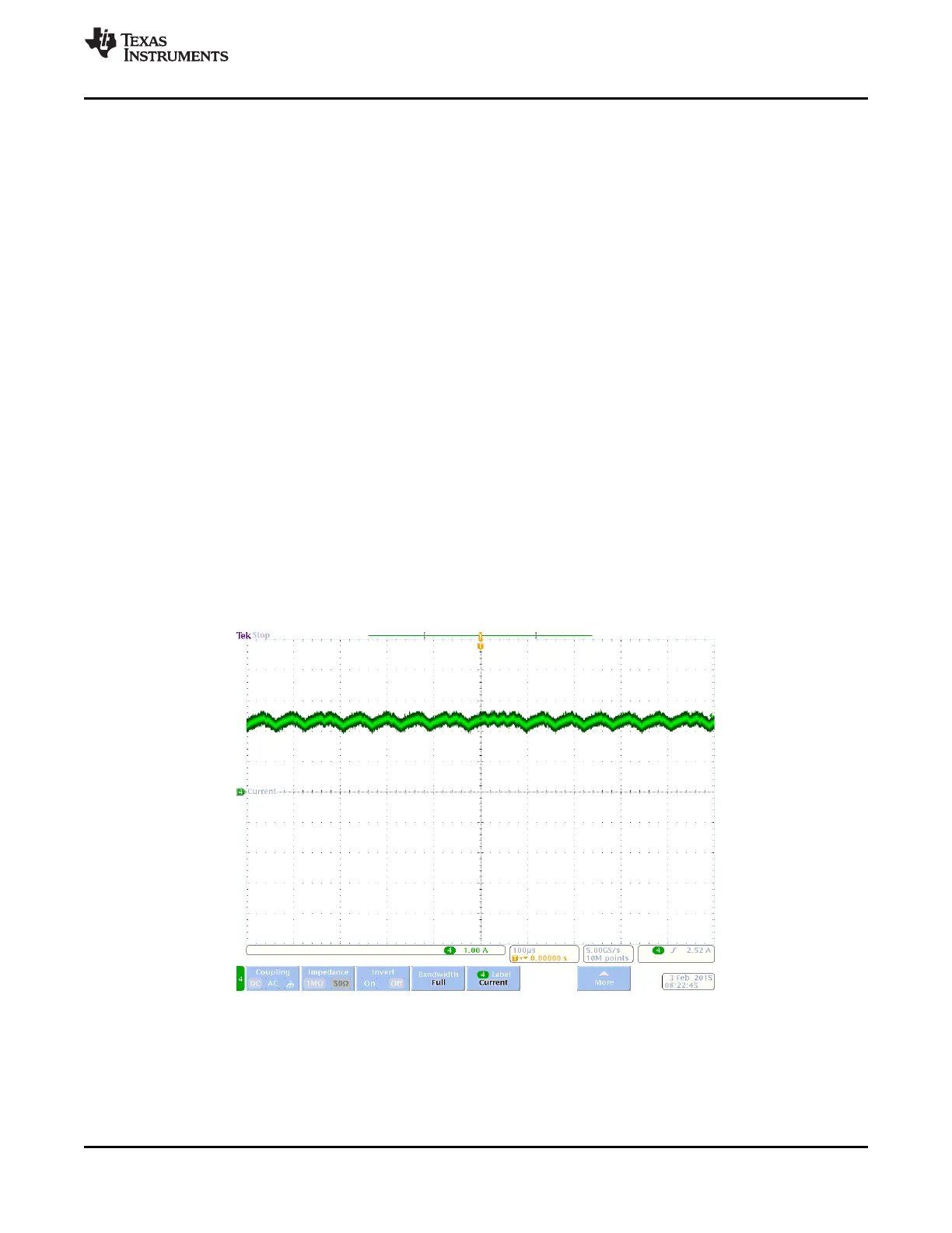
8.2.3 Application Curve
Figure 8. Current Regulation
Copyright © 2011–2015, Texas Instruments Incorporated Submit Documentation Feedback 13
Product Folder Links: DRV8833