VM
11
C1
0.01uF
C4
10uF
+
12
VM
VCP
AIN1
AIN2
U1
DRV8833
M
From Controller
I 1N
IN2
LOW = SLEEP, HIGH = RUN
1
10
9
15
BIN1
BIN2
NSLEEP
AOUT1
AOUT2
BOUT1
BOUT2
NFAULT
VINT
AISEN
BISEN
GNDP
GND
2
4
7
5
8
14
3
6
C2
2.2uF
R2
200m
13
PP
16
DRV8833
SLVSAR1E –JANUARY 2011–REVISED JULY 2015
www.ti.com
8 Application and Implementation
NOTE
Information in the following applications sections is not part of the TI component
specification, and TI does not warrant its accuracy or completeness. TI’s customers are
responsible for determining suitability of components for their purposes. Customers should
validate and test their design implementation to confirm system functionality.
8.1 Application Information
The DRV8833 is used in brushed DC or stepper motor control. The following design procedure can be used to
configure the DRV8833 in a brushed DC motor application. The inputs and outputs are connected in parallel to
achieve higher current.
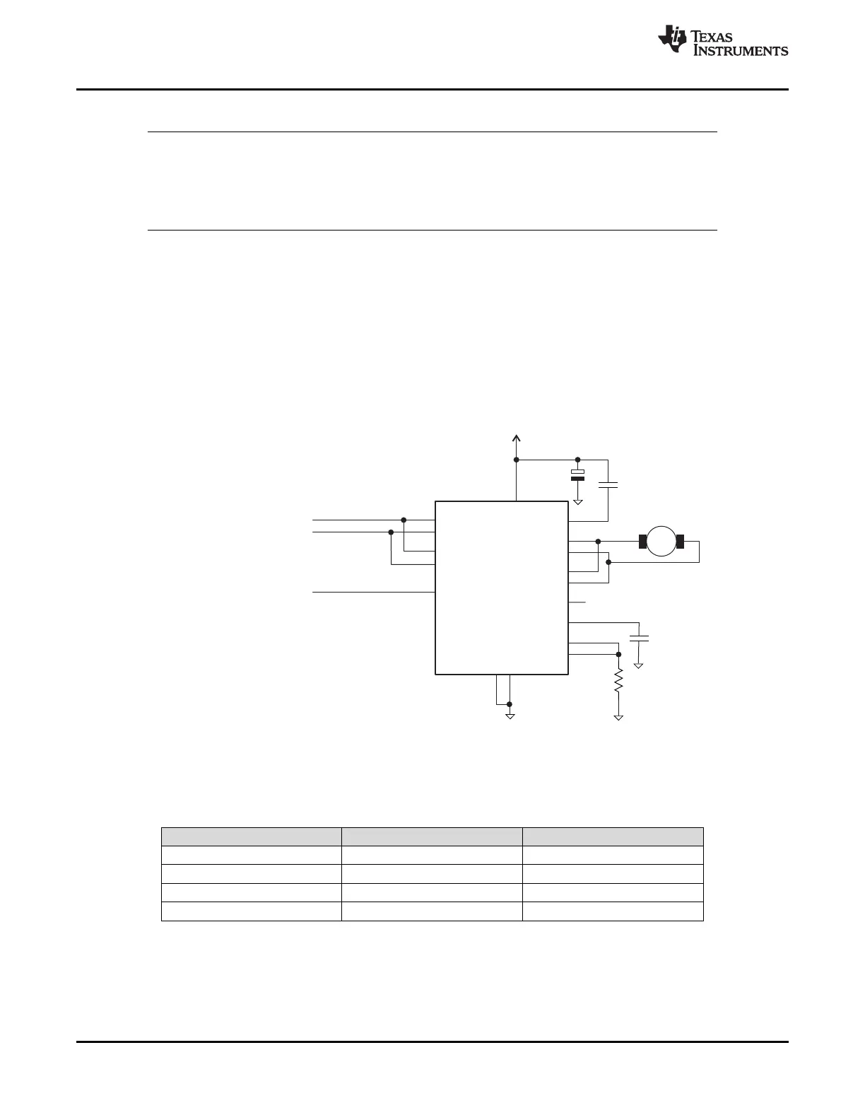
8.2 Typical Application
The two H-bridges in the DRV8833 can be connected in parallel for double the current of a single H-bridge. The
internal dead time in the DRV8833 prevents any risk of cross-conduction (shoot-through) between the two
bridges due to timing differences between the two bridges. Figure 7 shows the connections.
Figure 7. Parallel Mode
8.2.1 Design Requirements
Table 5. Design Parameters
DESIGN PARAMETER REFERENCE EXAMPLE VALUE
Motor voltage V
M
10 V
Motor RMS current I
RMS
0.8 A
Motor start-up current I
START
2 A
Motor current trip point I
TRIP
2.5 A
8.2.2 Detailed Design Procedure
8.2.2.1 Motor Voltage
The motor voltage to use will depend on the ratings of the motor selected and the desired RPM. A higher voltage
spins a brushed DC motor faster with the same PWM duty cycle applied to the power FETs. A higher voltage
also increases the rate of current change through the inductive motor windings.
12 Submit Documentation Feedback Copyright © 2011–2015, Texas Instruments Incorporated
Product Folder Links: DRV8833