xOUT1
xOUT2
VM
xISEN
xIN2
Pre-
drive
VCP, VINT
VM
+
-
PWM
OCP
OCP
xIN1
REF (200mV)
DCM
Optional
DRV8833
www.ti.com
SLVSAR1E –JANUARY 2011–REVISED JULY 2015
7.3 Feature Description
7.3.1 Fixed-Frequency PWM Motor Drivers
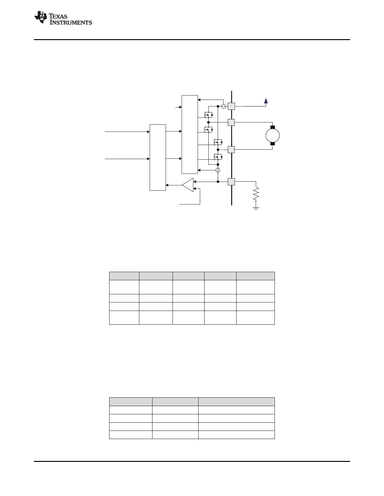
DRV8833 contains two identical H-bridge motor drivers with current-control PWM circuitry. Figure 5 shows a
block diagram of the circuitry.
Figure 5. Motor Control Circuitry
7.3.2 Bridge Control and Decay Modes
The AIN1 and AIN2 input pins control the state of the AOUT1 and AOUT2 outputs; similarly, the BIN1 and BIN2
input pins control the state of the BOUT1 and BOUT2 outputs. Table 1 shows the logic.
Table 1. H-Bridge Logic
xIN1 xIN2 xOUT1 xOUT2 FUNCTION
Coast/fast
0 0 Z Z
decay
0 1 L H Reverse
1 0 H L Forward
Brake/slow
1 1 L L
decay
The inputs can also be used for PWM control of the motor speed. When controlling a winding with PWM, when
the drive current is interrupted, the inductive nature of the motor requires that the current must continue to flow.
This is called recirculation current. To handle this recirculation current, the H-bridge can operate in two different
states: fast decay or slow decay. In fast decay mode, the H-bridge is disabled and recirculation current flows
through the body diodes; in slow decay, the motor winding is shorted.
To PWM using fast decay, the PWM signal is applied to one xIN pin while the other is held low; to use slow
decay, one xIN pin is held high.
Table 2. PWM Control of Motor Speed
xIN1 xIN2 FUNCTION
PWM 0 Forward PWM, fast decay
1 PWM Forward PWM, slow decay
0 PWM Reverse PWM, fast decay
PWM 1 Reverse PWM, slow decay
Copyright © 2011–2015, Texas Instruments Incorporated Submit Documentation Feedback 9
Product Folder Links: DRV8833