xOUT1
xOUT2
1
2
3
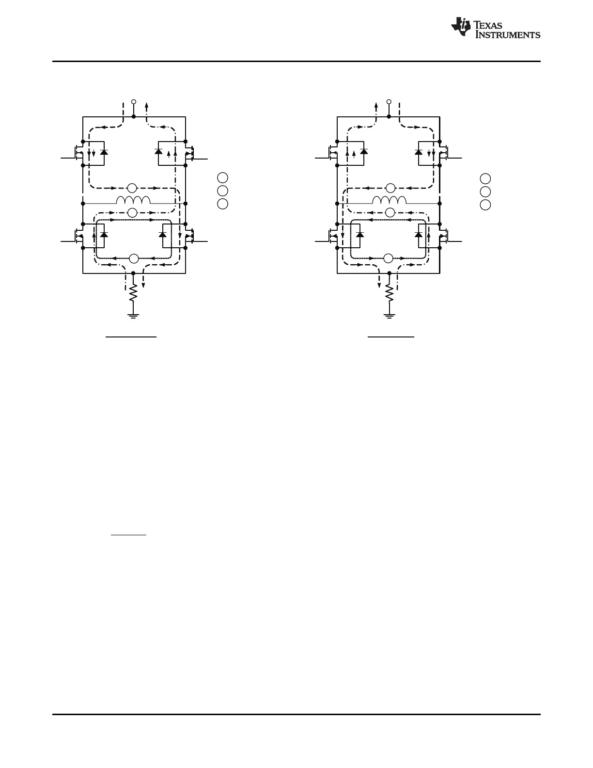
Forward drive
Slow decay
Fast decay
VM
1
2
1
2
3
Reverse drive
Slow decay
Fast decay
xOUT1 xOUT2
3
VM
1
2
3
FORWARD REVERSE
DRV8833
SLVSAR1E –JANUARY 2011–REVISED JULY 2015
www.ti.com
Figure 6 shows the current paths in different drive and decay modes.
Figure 6. Drive and Decay Modes
7.3.3 Current Control
The current through the motor windings may be limited, or controlled, by a fixed-frequency PWM current
regulation, or current chopping. For DC motors, current control is used to limit the start-up and stall current of the
motor. For stepper motors, current control is often used at all times.
When an H-bridge is enabled, current rises through the winding at a rate dependent on the DC voltage and
inductance of the winding. If the current reaches the current chopping threshold, the bridge disables the current
until the beginning of the next PWM cycle. Immediately after the current is enabled, the voltage on the xISEN pin
is ignored for a fixed period of time before enabling the current sense circuitry. This blanking time is fixed at 3.75
μs. This blanking time also sets the minimum on time of the PWM when operating in current chopping mode.
The PWM chopping current is set by a comparator which compares the voltage across a current sense resistor
connected to the xISEN pins with a reference voltage. The reference voltage is fixed at 200 mV.
The chopping current is calculated in Equation 1.
(1)
Example: If a 1-Ω sense resistor is used, the chopping current will be 200 mV/1 Ω = 200 mA.
Once the chopping current threshold is reached, the H-bridge switches to slow decay mode. Winding current is
recirculated by enabling both of the low-side FETs in the bridge. This state is held until the beginning of the next
fixed-frequency PWM cycle.
If current control is not needed, the xISEN pins should be connected directly to ground.
10 Submit Documentation Feedback Copyright © 2011–2015, Texas Instruments Incorporated
Product Folder Links: DRV8833