Over-
Temp
AOUT1
GND
AIN1
VM
Logic
AOUT2
VM
Gate
Drive
&
OCP
BOUT1
VM
BOUT2
VM
Gate
Drive
&
OCP
BISEN
AISEN
Step
Motor
Drives 2x DC motor
or 1x Stepper
ISEN
ISEN
AIN2
BIN1
BIN2
Charge
Pump
0.01uF
VM
VM
VCP
VM
Internal
Ref &
Regs
VINT
DCM
DCM
nFAULT
nSLEEP
2.2uF
10uF
DRV8833
SLVSAR1E –JANUARY 2011–REVISED JULY 2015
www.ti.com
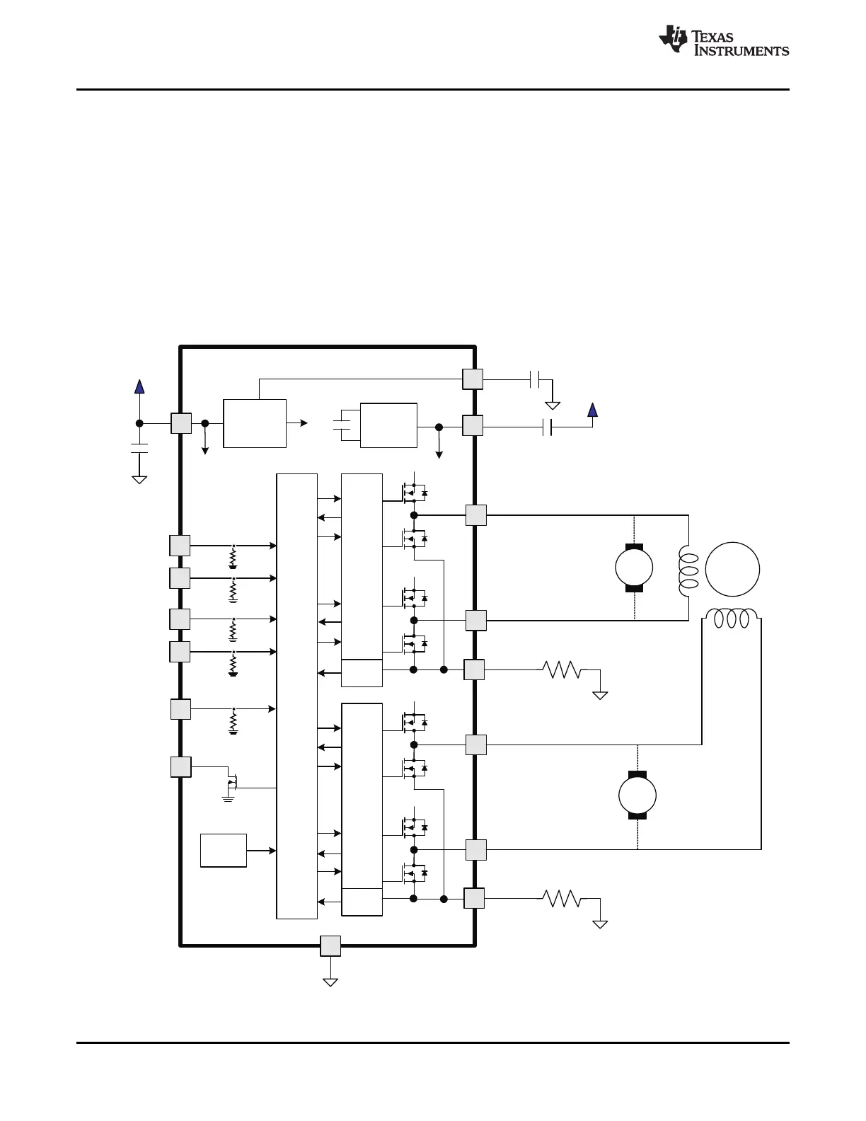
7 Detailed Description
7.1 Overview
The DRV8833 device is an integrated motor driver solution for brushed DC or bipolar stepper motors. The device
integrates two NMOS H-bridges and current regulation circuitry. The DRV8833 can be powered with a supply
voltage from 2.7 to 10.8 V and can provide an output current up to 1.5-A RMS.
A simple PWM interface allows easy interfacing to the controller circuit.
The current regulation is a fixed frequency PWM slow decay.
The device includes a low-power sleep mode, which lets the system save power when not driving the motor.
7.2 Functional Block Diagram
8 Submit Documentation Feedback Copyright © 2011–2015, Texas Instruments Incorporated
Product Folder Links: DRV8833