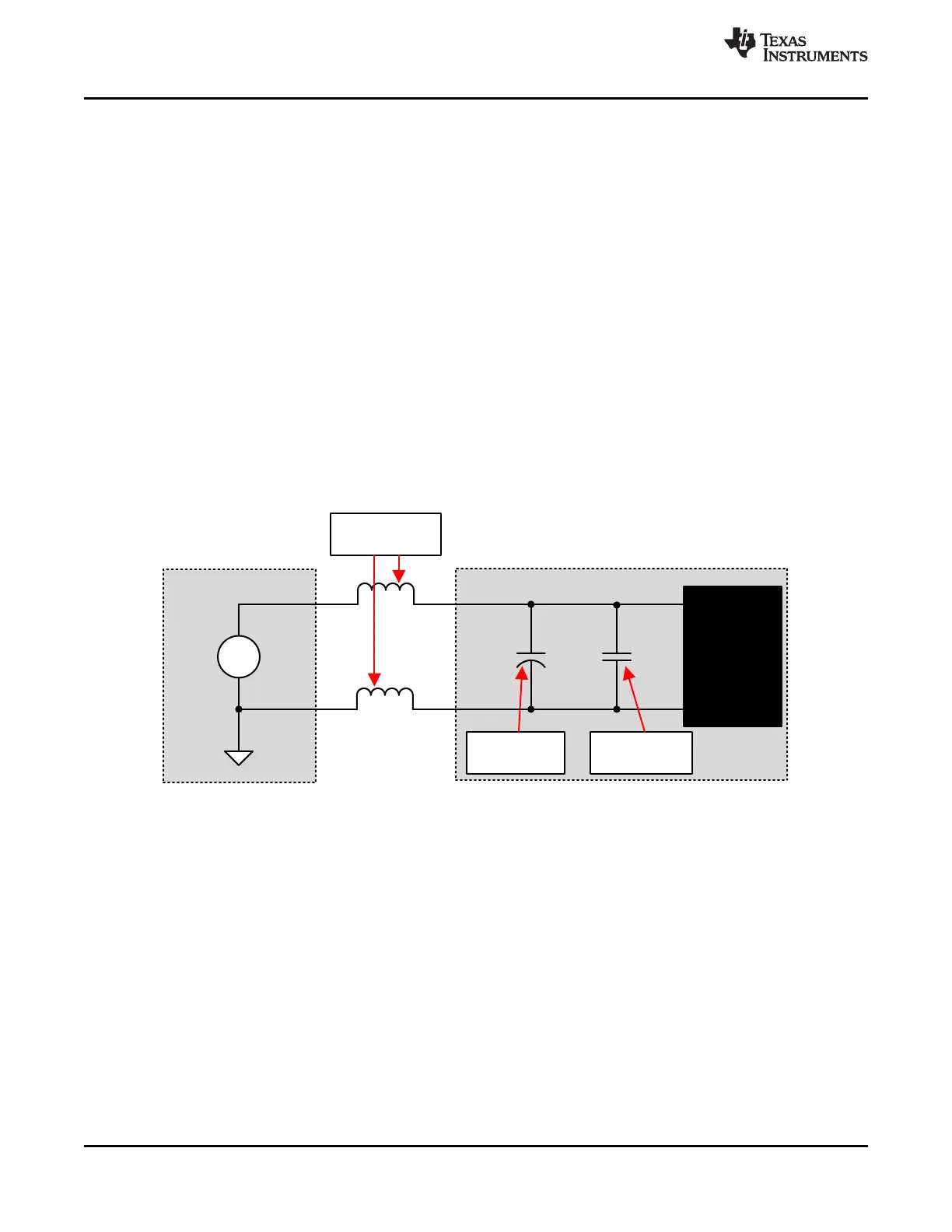
Local
Bulk Capacitor
Parasitic Wire
Inductance
+
±
Motor
Driver
Power Supply
Motor Drive System
VM
GND
+
IC Bypass
Capacitor
DRV8833
SLVSAR1E –JANUARY 2011–REVISED JULY 2015
www.ti.com
9 Power Supply Recommendations
9.1 Bulk Capacitance
Having an appropriate local bulk capacitance is an important factor in motor drive system design. It is generally
beneficial to have more bulk capacitance, while the disadvantages are increased cost and physical size.
The amount of local capacitance needed depends on a variety of factors, including:
• The highest current required by the motor system
• The capacitance and ability to source current
• The amount of parasitic inductance between the power supply and motor system
• The acceptable voltage ripple
• The type of motor used (brushed DC, brushless DC, stepper)
• The motor braking method
The inductance between the power supply and the motor drive system limits the rate current can change from
the power supply. If the local bulk capacitance is too small, the system responds to excessive current demands
or dumps from the motor with a change in voltage. When adequate bulk capacitance is used, the motor voltage
remains stable and high current can be quickly supplied.
The data sheet generally provides a recommended value, but system-level testing is required to determine the
appropriate sized bulk capacitor.
Figure 9. Example Setup of Motor Drive System With External Power Supply
The voltage rating for bulk capacitors should be higher than the operating voltage, to provide margin for cases
when the motor transfers energy to the supply.
9.2 Power Supply and Logic Sequencing
There is no specific sequence for powering up the DRV8833. The presence of digital input signals is acceptable
before VM is applied. After VM is applied to the DRV8833, the device begins operation based on the status of
the control pins.
14 Submit Documentation Feedback Copyright © 2011–2015, Texas Instruments Incorporated
Product Folder Links: DRV8833