Hardware
www.ti.com
14
SPRUIM4B–December 2018–Revised May 2020
Submit Documentation Feedback
Copyright © 2018–2020, Texas Instruments Incorporated
xWR1843 Evaluation Module (xWR1843BOOST) Single-Chip mmWave
Sensing Solution
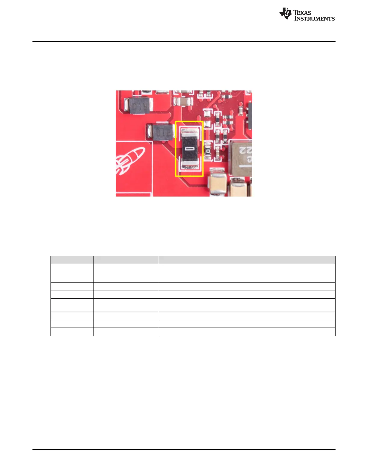
2.8.2 Current Measurement
The R156 resistor enables the measurement of the current being consumed by the reference design
(AWR device, PMIC, and LDOs) at a 3.3-V level.
To measure the current, resistor R156 must be removed and a series ammeter can be put across the
resistor pins (shown in Figure 14).
Figure 14. Current Measure Resistor
2.8.3 Push Buttons and LEDs
Table 5 provides the switch and LED information.
Table 5. Switch and LED Information
Reference Usage Comments
SW2 RESET
Used to RESET the xWR1843 device. This signal is also brought out on the 20-
pin connector and 60-pin HD connector so an external processor can control the
AWR device. The onboard XDS110 can also use this reset.
SW1 GPIO_1 When pushed, the GPIO_1 is pulled to V
CC
.
DS2 Warm reset indication This LED indicates the warm reset is triggered.
DS4 nRESET
This LED is used to indicate the state of nRESET pin. If this LED is glowing, the
device is out of reset. This LED will glow only after the 5-V supply is provided.
DS1 Nerr_OUT Glows if there is any HW error in the AWR device
DS3 GPIO_1 Glows when the GPIO is logic-1
D5 PWR This LED indicates the presence of the 3.3-V supply

 Loading...


