www.ti.com
Hardware
15
SPRUIM4B–December 2018–Revised May 2020
Submit Documentation Feedback
Copyright © 2018–2020, Texas Instruments Incorporated
xWR1843 Evaluation Module (xWR1843BOOST) Single-Chip mmWave
Sensing Solution
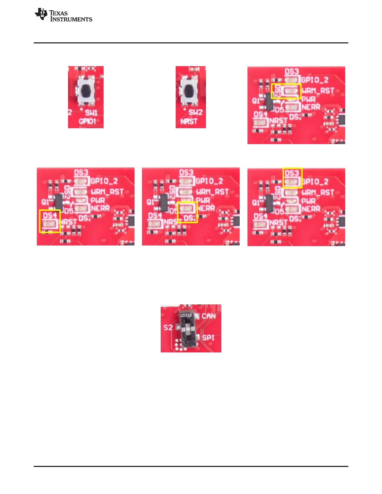
Figure 15 through Figure 20 show the location of switches and LEDs.
Figure 15. SW1 Figure 16. SW2 Figure 17. DS2
Figure 18. DS4 Figure 19. DS1 Figure 20. DS3
2.8.4 Selection Between SPI and CAN Interface
The SPI and CAN interface are muxed on the same lines on the xWR1843 device. Based on the
configuration, the user can select if the pins E14 and D13 must be connected to the 20-pin/HD connectors
to provide the SPI interface OR to the onboard CANFD PHY (U3). This selection is done by the S2 switch.
Figure 21. S2 Switch to Select Between SPI or CAN Interface

 Loading...


