Getting Started with 4G Modem Card
3.3 Power Supply Configuration
16
t MLx31_startup_guide_v01 2021-05-06
Confidential / Prelimenary
Page 15 of 17
3.2.1 USB Variant
3.3 Power Supply Configuration
The 4G Modem Card Adapter Board can be powered over USB3.0, PCIe interface or by an
external power supply. For configuration see Table 2
For the position of the Jumpers see Figure 4.
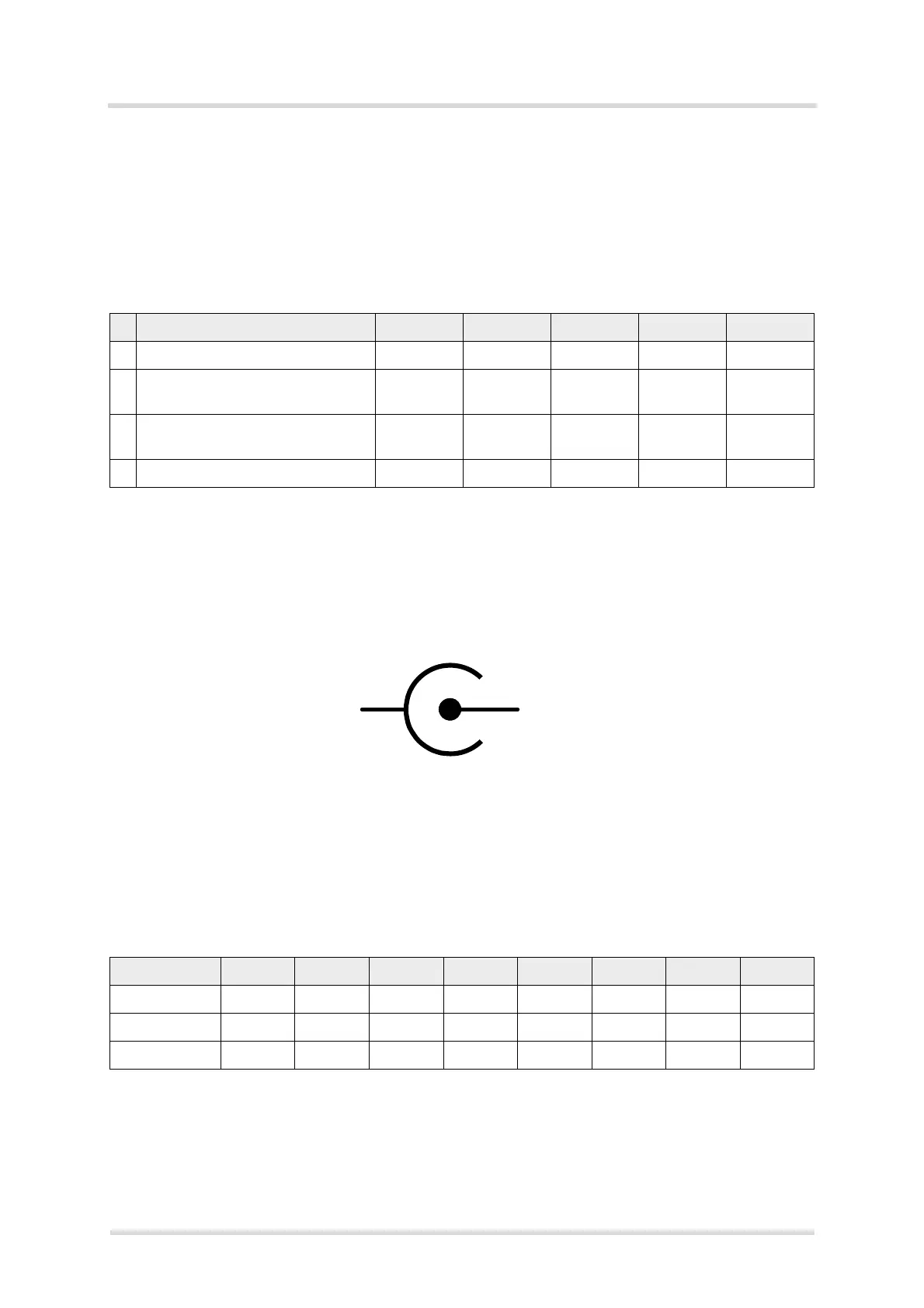
To connect an external 12V DC power supply with the 4G Modem Card Adapter Board, the ex-
ternal power supply should have a co-axial power plug with 5.5 mm (0.22 in) in outside diam-
eter and a pin sizes of 2.5 mm (0.098 in).
Figure 5: Polarity of 12V DC Jack
3.4 Configuration Switches and Jumper
The following Table 3 show the recommended switch configuration.
The Table 4 shows the detailed function of the required switches.
Table 2: Power Supply Configurations
J1 J2 J3 J4 J5
1 Powered by USB3.0 mounted mounted mounted removed removed
2 Powered by PCIe Interface
(Golden Finger)
removed mounted mounted mounted removed
3 Powered external 12V
(see Figure 5)
removed mounted mounted removed mounted
4 Bypass 3.3V voltage regulator removed inject PIN1 mounted removed removed
Table 3: Switch Configuration U206
1 2 3 4 5 6 7 8
Catch Logs --
1
1.
Switch 1-4 can have the setting for ANTCTL or PCM
--
1
--
1
--
1
OFF ON OFF ON
ANTCTL OFF ON OFF ON ON OFF ON OFF
PCM ON OFF ON OFF --
2
2.
Switch 5-8 can have the setting for Catch Logs or ANTCTL
--
2
--
2
--
2

 Loading...