Getting Started with 4G Modem Card
3.5 Additional Connector
16
t MLx31_startup_guide_v01 2021-05-06
Confidential / Prelimenary
Page 16 of 17
For the position of the switches see Figure 4.
For MLP31-W only:
Jumper 6 selects between 4x4 MIMO and 2x2 MIMO.
For the position of Jumper J6 see Figure 4.
3.5 Additional Connector
J211 (Table 6) provides additional signals, which are not available at the standard interfaces.
For the position of J211 see Figure 4.
Table 4: Switch Configuration in detail
Switch Block Switch Function when ON Delivery State
U206 1 PCM_DOUT OFF
2 ANTCTL_0 OFF
3 PCM_CLK OFF
4 ANTCTL_1 OFF
5 ANTCTL2 OFF
6 UART_RX1 OFF
7 ANTCTL3 OFF
8 UART_TX1 OFF
Table 5: Antenna configuration J6
J6 Description
mounted 4x4 MIMO antennas
unmounted 2x2 MIMO antennas
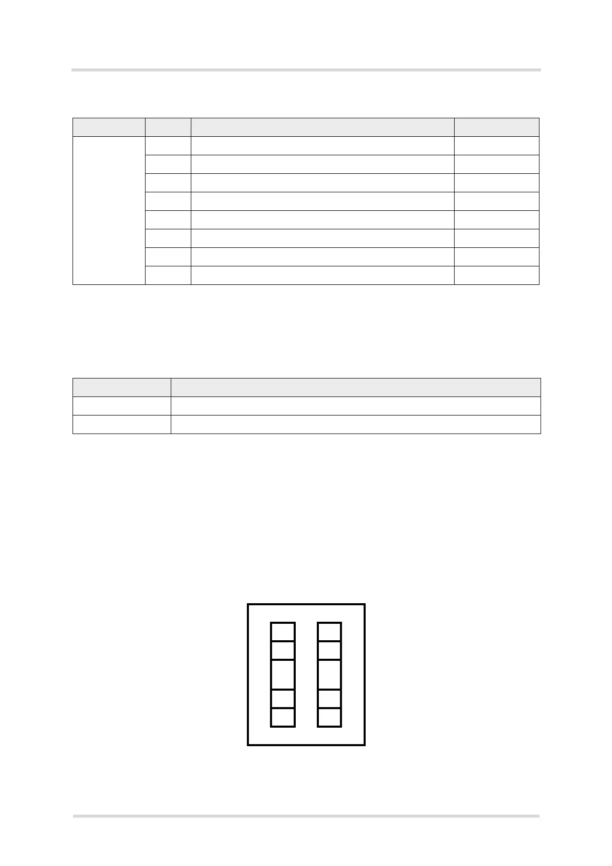
Table 6: Signals at Jumper on J211
Signal J211 Signal
MCLK 1 2 RFFE2_DATA
PCM_DOUT 3 4 RFFE2_CLK
PCM_CLK 5 6 PMIC_GPIO6
(ANT_TUNER_CONFIG)
PCM_SYNC 7 8 COEX_UART_RX
PCM_DIN 9 10 COEX_UART_TX
 Loading...