ACHAT DSP24 • OWNER’S MANUAL
4
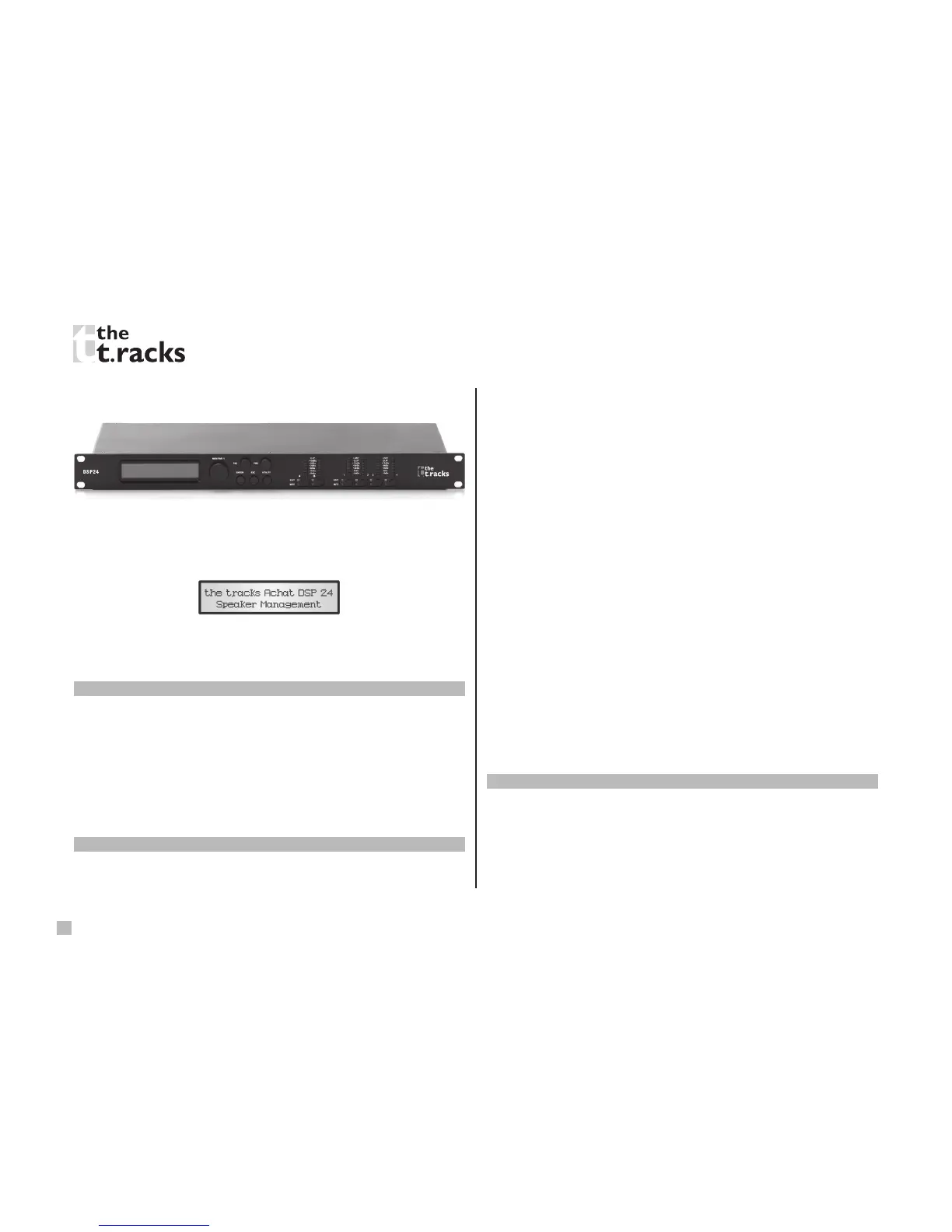
Described below are the functions of the front panel control
buttons and encoders for DSP24.
Getting started
As soon as the unit is turned ON the device model name will
appear in the display:
After the initialization, the unit will show the name of the
previously selected program on the LCD prior to the unit being
turned off.
Encoders and ENTER, ESC buttons
The DSP24 is equipped with 3 relative encoders, “NAV/PM1”,
“PM2” and “PM3”. These encoders allow you to navigate the
user interface and edit sections of the processor. They allow
the user to navigate within the screen for the selection of sub-
menus, pages and parameters and to select the values to be
assigned during the editing operations.
The “ENTER” and “ESC” buttons allow the user to conrm or
NOT conrm the operations performed by the encoders.
UTILITY, A/B and 1/2/3/4 buttons
The UTILITY button allows the user to enter the sub-menus and
to set the general characteristics of the processor. Buttons A and
B allow the user to enter the editing menus of the processor’s
input channels. Buttons 1, 2, 3, and 4 allow the user to enter
the editing menus of the processor’s output channels.
Buttons A and B as well as the 1, 2, 3, and 4 buttons have
double functions dependent on the push and hold time.
When buttons A and B are pushed and held for more than one
second, input channels A or B are either muted or un-muted.
The red LED will illuminate when the channel is muted. When
the “MUTE” LED is off, then the related input channel is un-muted.
A brief push of the A and B buttons enters the editing mode
for the input channels (see later for the input channel editing
details). The blue “EDIT” LED will now be on.
When the 1, 2, 3, and 4 buttons are pushed and held for more
than one second the output channels 1, 2, 3, and 4 are either
muted or un-muted. The red LED will illuminate when the
channel is muted. When the “MUTE” LED is off, then the related
output channel is un-muted.
A brief push of the 1, 2, 3 and 4 buttons enters the editing
menu for the output channels (see later for the output channel
editing details). The blue “EDIT” LED will now be on.
DSP24 menu and sub-menu structures
From the default display, sub-menus are accessed using the
“UTILITY”, “A/B”, “1/2/3/4”, “ENTER” and “ESC” buttons and
all parameters and values are navigated by the “NAV/PM1”,
“PM2” and “PM3” encoders. Please refer to the following menu
structures:
 Loading...