Do you have a question about the Thermal Arc Viking 210GM and is the answer not in the manual?
Explains how notes, cautions, and warnings are categorized in the manual.
General safety precautions for operating welding arc equipment.
Lists standards and publications for further safety and welding information.
Details the limited warranty terms, limitations, and exclusions for the welding equipment.
Outlines basic safety rules that should always be followed during operation.
Explains the function of protective filter lenses and their importance for eye safety.
Recommends using a welding helmet with the correct filter lens for electric arc welding.
Defines user responsibilities for proper installation, operation, maintenance, and modification of the equipment.
Explains the concept of duty cycle for welding power sources and its implications for operation.
Lists the specifications for the TWECO MIG torch, including part numbers and cable length.
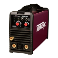
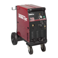
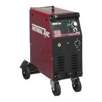
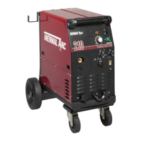
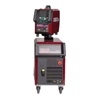
Provides detailed specifications for Viking 210GM/RGM and 250GM/RGM models, including dimensions, voltage, and current ratings.
Details specifications related to the wire drive system, including wire speed, diameter, and spool size.
Lists the standard items included in the Viking 210 and 250 power supply packages.
Lists optional accessories available for the Viking 210GM and 250GM models, with catalogue numbers.
Describes suitable environmental conditions and hazards to avoid during installation.
Provides guidelines for selecting an appropriate location for the power source, considering airflow and safety.
Emphasizes the need for effective ventilation due to potentially harmful welding fumes.
Details mains supply voltage requirements and potential issues with incorrect voltages.
Lists alternative mains supply voltages and corresponding lead sizes and fuse requirements.
Describes the function of the indicator light and its connection to the mains supply voltage.
Explains the operation of coarse and fine voltage control switches for setting welding voltage.
Details the optional digital ammeter and voltmeter for monitoring welding current and voltage.
Explains how to use the torch polarity lead to select the welding voltage polarity.
Describes the function of the heavy-duty bayonet type welding terminals for current flow.
Explains the use of the wirefeeder control socket for connecting the wirefeeder control cable.
Describes the thermal overload protection mechanism and procedure for cooling the machine.
Explains the selection of inductance taps for controlling spatter and penetration.
Details the wirespeed control knob for adjusting welding current via wire feed rate.
Explains the function of the spot timer knob for controlling single spot weld duration.
Describes the dwell timer knob for controlling the interval or 'OFF' time in stitch welding.
Explains how the mode selector switch is used to choose between SPOT, CONTINUOUS, and STITCH welding modes.
Details how to adjust the wirefeeder drive roller pressure for optimal wire feeding.
Explains the adjustment of the wire reel brake for proper wire tension during feeding.
Introduces the TWECO MIG torch and its benefits for Viking welders.
Lists and identifies the various components of the TWECO MIG torch.
Details consumable parts for TWECO MIG torches, including gas diffusers, contact tips, nozzles, and conduits.
Provides step-by-step instructions for installing a new wire conduit in the MIG torch cable.
Explains how to set welding current and voltage using Wirespeed and Voltage Control switches.
Discusses the effect of MIG torch angle on weld width.
Specifies the recommended electrode stick-out distance from the MIG torch nozzle.
Explains how travel speed influences weld width and penetration.
Lists factors influencing the choice of electrode wire size and shielding gas.
Guides on setting controls for stitch welding to bridge gaps or weld thin material.
Details how to set controls for spot welding operations using the MIG torch.
Provides a procedure for calibrating the digital meter for improved current accuracy.
Offers troubleshooting steps for common GMAW problems like porosity and inconsistent wire feed.
Lists common welding faults, their causes, and recommended remedies.
Identifies common power source issues, their causes, and solutions.
Lists key spare parts for Viking 210GM and 250GM models with part numbers.
| Input Voltage | 120/230V |
|---|---|
| Input Phase | Single Phase |
| Input Frequency | 50/60 Hz |
| Output Amperage Range (Stick) | 5-210A |
| Output Amperage Range (TIG) | 5-210A |
| Output Amperage Range (MIG) | 30-210A |
| Rated Output (230V) | 210A @ 26V |
| Processes | MIG, Stick, TIG |
| Duty Cycle (Stick @ 210A) | 20% |
| Duty Cycle (TIG @ 210A) | 20% |
| Duty Cycle (MIG @ 210A) | 20% |