11
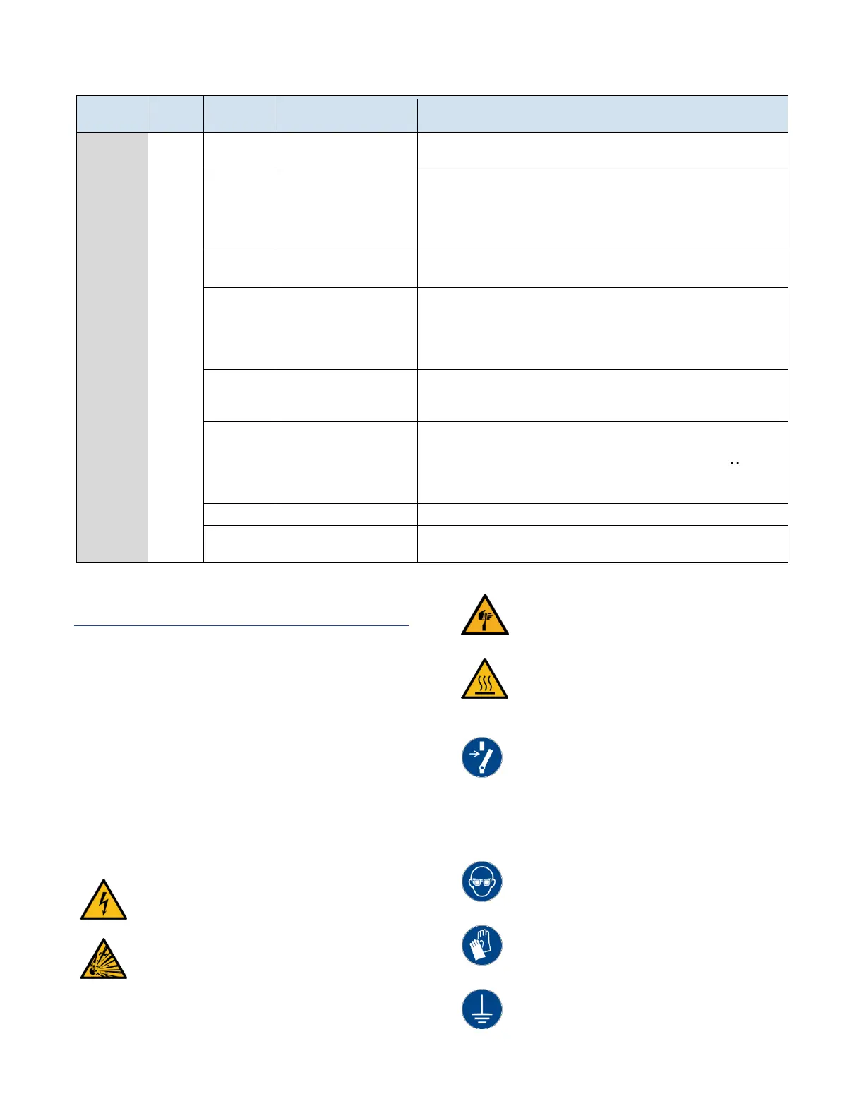
Table 3 – Diagnostic Screens (continued)
Temperature
Loop
Monitoring
Proportional Output
Contribution
The component of the PID output generated from proportional control.
Integral Output
Contribution
The component of the PID output generated from integral control. A ↕
symbol means this value is free to change because the integrator is
active; alternatively a Ä symbol means the integrator value is frozen due
to output saturation (anti-windup), or a large difference between process
value and setpoint.
Derivative Output
Contribution
The component of the PID output generated from derivative control.
This multiplier is applied to the sum of the P, I, and D contributions to
generate the output percentage. It dynamically changes in proportion to
the difference between cooling water temperature and process
temperature. The aggressiveness of this multiplier is set by the factory
parameter "Cool-Heat Rto".
The final output of the PID loop. This value drives the PWM generator for
either the cooling valve or heater. PWM generator outputs under 5% are
rounded to 0%, and outputs above 95% are rounded to 100%.
The current process value. By default, the controlling process value, as
determined by user parameter "PV Source," will be shown. Temporarily
view the other RTD temperature probe values by pressing the key (this
will not alter which RTD is actually controlling the PID loop). The display
reverts back to the controlling RTD after several seconds.
Process setpoint. This can be modified by pushing the ↑ or ↓ keys.
This is the difference between the process value and the setpoint. The
goal of the control loop is to reduce this to 0° during operation.
Start-up
Every unit is factory set to deliver water in
accordance with the standard operating
specifications for that particular unit. Due to
variables involved with different applications and
different installations, minor adjustments may be
required during the initial start-up to ensure proper
operation. Use a qualified technician to perform the
start-up procedure in sequence. The following serves
as a checklist for the initial start-up and for
subsequent start-ups if the unit is out of service for a
prolonged time.
WARNING: This equipment contains hazardous
voltages that can cause severe injury or death.
WARNING: This equipment contains hot water or
coolant under pressure. Accidental release of hot water
or coolant under pressure can cause personal injury
and or property damage.
WARNING: This equipment may contain fan blades or
other sharp edges. Make sure all fan guards and other
protective shields are securely in place.
WARNING: The exposed surfaces of motors, piping,
and other fluid circuit components can be very hot
and can cause burns if touched with unprotected
hands.
CAUTION: Disconnect and lock out incoming power
before installing, servicing, or maintaining the
equipment. Connecting power to the main terminal
block energizes the entire electric circuitry of the unit.
Electric power at the main disconnect should be shut
off before opening access panels for repair or
maintenance.
CAUTION: Wear eye protection when installing,
maintaining, or repairing the equipment to protect
against any sparks, debris, or fluid leaks.
CAUTION: Wear protective gloves when installing,
maintaining, or repairing the equipment to protect
against any sparks, debris, or fluid leaks.
CAUTION: Wire the unit ground in compliance with
local and national codes.