Structural Maintenance 12-24
Gear Motor Adjustment Procedure
The gear motor adjustment is only required if the assembly is removed or replaced, once correctly set it will not require further
adjustment.
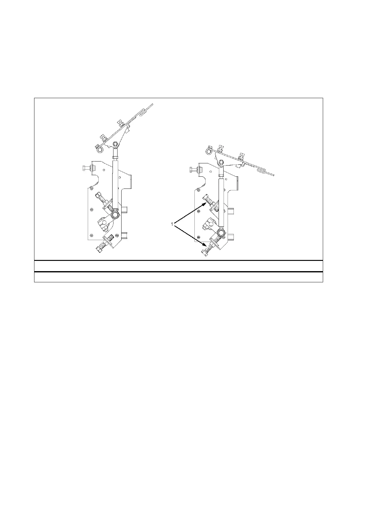
Install the Gear Motor and linkage in the position indicated in the attached drawings, note the linkage assembly orientation layout
and the limit stop bolts. See Figures 1 to 4 on the following pages.
Plug the Gear Motor wire connector into the harness connector.
The door may be at any random position.
Adjust the door to correctly open and close and set the limit stops as follows:
1. Loosen off the two 8 mm limit stop adjusting bolts.
2. Disconnect the “A”, “B” and “+” wires from the controller.
3. Jumper a #2 wire circuit (battery +) to terminal “B” on the controller.
4. The motor will operate and the door will open until the damper blade touches the air discharge housing. The motor bracket
and damper door will bend slightly until the controller senses a rise in motor current and will switch off.
5. Screw in the 8 mm open side limit stop bolt until it just touches the linkage crank arm; turn in a further 1 turn.
6. Operate the door to close and reopen and observe the operation.
7. The motor bracket should not noticeably move and the damper blade should lightly touch the air discharge anti-ice strip.
8. This will set the damper blade to touch the air discharge anti-ice strip and the limit stop bolt simultaneously.
9. Tighten the open side limit stop bolt lock nut and re-check the operation.
10. Jumper a #2 wire circuit (battery +) to terminal “A” on the controller.
11. The motor will operate and the damper door will move to the close position.
12. The damper blade neoprene air seal will press into the air discharge housing making a tight seal against the housing. The motor
bracket will bend slightly until the controller senses a rise in motor current and will switch off.
13. Screw in the 8 mm close side limit stop bolt until it just touches the linkage crank arm; turn in a further 1 turn.
14. Operate the door to open and close and observe the operation.
15. Adjust the 8 mm screw until the damper door blade neoprene seal makes a light but uniform contact with the air discharge
housing.
16. Tighten the close side limit stop bolt lock nut.
17. Repeat the opening and closing operation ensuring the damper blade seal neoprene and the limit stops make simultaneous
contact giving a light and uniform air seal.
Figure 1
1. Limit Stop Bolts
CLOSED POSITION OPEN POSITION
A
B



 To Next Page