Do you have a question about the Thermo King V-520 and is the answer not in the manual?
Summary of manual updates and changes, including format and content revisions.
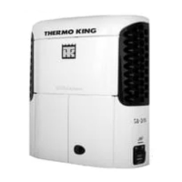
Overview of unit models covered and references for further information.
Defines hazard advisory types for safe operation and potential risks.
Guidelines for required protective gear and safety practices during servicing.
Describes risks associated with refrigerant handling, storage, and safety precautions.
Outlines dangers and precautions for working with high and low voltage electrical systems.
Lists V-520 models, system numbers, install kits, refrigerants, and diagrams.
Details fuse specifications, component currents, and resistances.
Lists refrigerant charge amounts and system pressure settings for various models.
Provides specifications for compressor types, oil capacity, and clutch data.
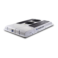
Overview of V-520 and V-520 MAX truck refrigeration systems and their design.
Lists key features included as standard on the refrigeration units.
Describes the main engine-driven and electric standby compressor functions.
Details refrigerants used (R-134a, R-404A, R-452A) and their applications.
Explains how the unit operates in different modes like Cool, Heat, and Null.
Describes the cooling cycle, system operation, and fan control logic.
Explains the heating cycle, system operation, and solenoid functions.
Details the defrost cycle initiation, termination, and system actions.
Outlines daily, weekly, and periodic electrical system inspection tasks.
Lists maintenance tasks for refrigeration and heating systems.
Covers inspection of structural components, coils, and mounting hardware.
Explains the defrost system operation, initiation, and termination settings.
Identifies controller and harness fuse locations and ratings.
Details relay testing procedures, types, and replacement instructions.
Covers capacitor testing, replacement, and safety precautions.
Details testing procedures for 230/1/60 and 230/3/60 compressor motors.
Procedure to verify system refrigerant levels using sight glass and pressures.
Method for ensuring adequate compressor oil supply after refrigerant loss.
Steps for flushing the system and cleaning components after failure.
Removal and installation procedures for the system drier.
Procedure to test the hot gas solenoid valve operation.
Testing the liquid line solenoid for SPECTRUM unit operation.
Steps for removing and installing solenoid valves, including soldering precautions.
Testing and replacement procedures for the discharge check valve.
Procedures for removing and installing the evaporator coil.
Methods for testing engine-driven compressor performance and clutch.
Importance of correct pulley alignment and belt tension for compressor longevity.
Recommendations and methods for cleaning condenser and evaporator coils.
Troubleshooting steps for when the control box display does not activate.
Troubleshooting steps for when the unit fails to operate after display activation.
Troubleshooting for no display in electric standby mode.
Troubleshooting for compressor motor non-operation in standby mode.
Identifies possible causes and remedies for unit short cycling.
Diagnosis and solutions for elevated box temperatures.
Troubleshooting steps for issues causing high head pressure.
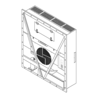
Lists relevant diagrams available for unit systems and their drawing numbers.
| Brand | Thermo King |
|---|---|
| Model | V-520 |
| Category | Air Conditioner |
| Language | English |