TK 54343-18-MM-EN
29
Refrigerant
IImmppoorrttaanntt::
MAX and SPECTRUM units built Before December 12, 2022 were originally built using R-404A refrigerant.
MAX and SPECTRUM units built on and after December 12, 2022 are equipped with R-452A refrigerant.
See Service Bulletin SB874 Transition to R–452A Refrigerant for Vehicle-Powered (VP) Truck Units in North
America
• V-520 10, V-520 20, V-520 30, and V-520 50 units use R-134a refrigerant.
• V-520 MAX 10, V-520 MAX 20, V-520 MAX 30, V-520 MAX 50, V-520 SPECTRUM 10, V-520 SPECTRUM 20, and V-520
SPECTRUM 50 units use R-404A or R-452A refrigerant.
Liquid Injection System
MAX units use R-404A or R-452A. These units have a liquid injection system to limit discharge temperature of the
engine driven compressor. Liquid injection is activated when the temperature switch is closed or when the unit is
running in heat mode on Model 30 and Model 50 units. If the discharge gas leaving the compressor reaches a
temperature of 230 ± 5 F (110 ± 3 C) the liquid injection switch closes, providing voltage to the liquid injection solenoid.
The solenoid opens a valve, allowing liquid refrigerant to flow from the liquid line in the evaporator to the metering
orifice. The metering orifice is attached to the suction tube assembly in the condenser. As the refrigerant passes
through the metering orifice it expands and evaporates, cooling the suction gas entering the compressor. This cooling
effect is transferred to the discharge gas leaving the compressor from the adjacent cavity in the compressor head.
When the discharge gas is cooled to 200 ± 5 F (93 ± 3 C), the liquid injection switch opens, the liquid injection solenoid
closes and refrigerant no longer flows through the liquid injection system.
Evaporator Drain Line Heaters
Evaporator drain line heaters are used in these units to avoid drain line blockage because of ice accumulation inside the
evaporator. Two harnesses are located inside the drain lines. These resistive wires melt the ice when energized/while in
defrost mode. These drain line heaters are standard on all MAX units, but can be an option with R-134A units. Please
contact your Thermo King Dealer for more information.
Electric Standby Operation
When the unit is connected to an electric power source, the battery relay is de-energized, and the standby relay is
energized to provide rectified power from the transformer to the electronic control system.
During electric standby operation, the electronic control system controls the operation of the unit by energizing and de-
energizing the compressor contactor and standby compressor clutch (if applicable) and places the unit in cool, heat, or
defrost mode by energizing the compressor contactor and standby compressor clutch (if applicable).
The electronic control system places the unit in null by de-energizing the compressor contactor and standby
compressor clutch.
Protection Features
• Discharge (High) Pressure Transducer - The discharge pressure transducer is a pressure sensitive device. It is
located in the condenser section discharge line near the oil separator.
If the discharge pressure rises above a certain pressure, the ECM opens the circuit to the compressor clutch to
stop unit operation.
For units with R-134a, the ECM opens the compressor clutch circuit at 300 psig (2068 kPa) and shuts down the
unit. The ECM closes the compressor clutch circuit when the pressure drops to 200 psig (1379 kPa).
For units with R-404A or R-452A, the ECM opens the compressor clutch circuit at 450 psig (3103 kPa) and shuts
down the unit. The ECM closes the compressor clutch circuit when the pressure drops to 375 psig (2586 kPa).
• Low Pressure Cutout Switch - The Low Pressure Cutout Switch is a pressure sensitive switch located on the suction
line assembly in the evaporator. If the suction pressure falls below 5 to 11 in. Hg vacuum (-17 to -34 kPa), the switch
opens the LPCO/CH circuit. This signals the ECM to open the circuit to the compressor clutch to stop unit operation.
The ECM closes the compressor clutch circuit when the pressure rises to 4 to 7 psig (28 to 48 kPa).
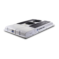
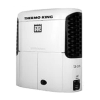
UUnniitt DDeessccrriippttiioonn
 Loading...