32
TK 54343-18-MM-EN
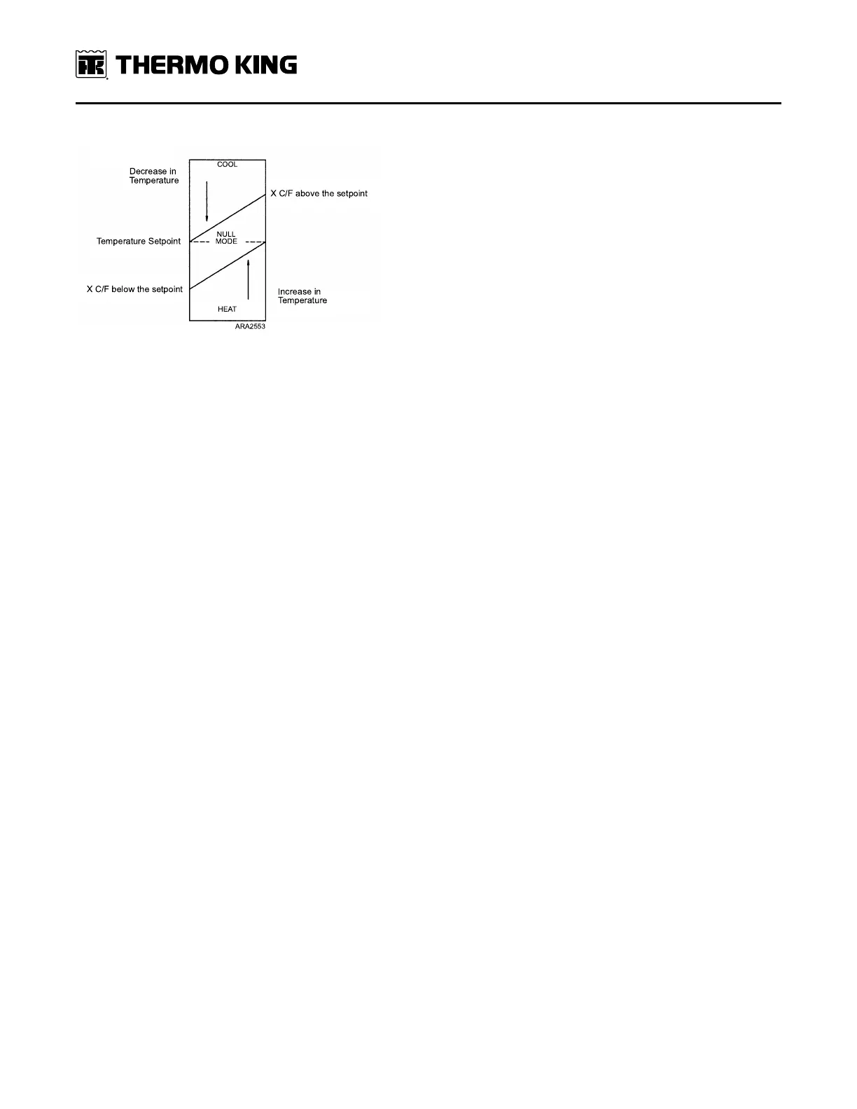
Figure 2. Thermostat Algorithm
For units with Electric Standby, there are protective delays for the electric compressor/compressor motor contactor.
Options:
• Coolant Heat - This option provides auxiliary heating by circulating hot engine coolant through the evaporator.
• Electric Heat - Provides auxiliary heat through resistive heat strips in the evaporator when connected to electric
standby.
• SPECTRUM - Provides temperature control for two-compartment systems.
Operation
The vehicle engine must be running and the unit must be turned on. On units with Electric Standby, connect the
external power cord and the unit switches to Electric mode operation. Unit operation can be tailored, as required, using
programmable settings as shown in the Direct Smart Reefer Microprocessor Control System Diagnostic Manual TK
52573.
Cool Mode
When cooling is required (when there is a requirement to lower the evaporator return air temperature in the load
compartment), the controller energizes the compressor clutch (or compressor motor contactor in Model 20/50 units)
and evaporator fans. The controller monitors the discharge pressure through the discharge pressure transducer (DPT).
The condenser fans are energized if necessary and turn on and off as determined by the controller.
In SPECTRUM units the controller also energizes the liquid line solenoid(s) in the compartment(s) that require cooling.
The unit operates in Cool mode until the setpoint temperature is reached. The unit then enters Null mode. When the
temperature rises to a pre-determined number of degrees (programmable setting), the unit restarts in Cool mode.
In SPECTRUM units the compartment operates in Cool mode until the setpoint temperature is reached. The
compartment then enters Null mode. When the temperature rises to a pre-determined number of degrees
(programmable setting), the compartment restarts in Cool mode. The compressor will stop if both compartments are in
Null.
These units have a triple-cooling capacity (TCC) feature. The controller monitors the discharge pressure through the
discharge pressure transducer (DPT) and controls the speed of condenser fans CF1 and CF2 by opening and closing
relays RY6, RY9, RY10 in the following manner:
• When the discharge pressure is less than 180 psig (1241 kPa), RY6, RY9, and RY10 are open. CF1 and CF2 receive no
voltage and are in Null state.
• When the discharge pressure is between 180 psig (1241 kPa) and 300 psig (2068 kPa), RY9 closes. CF1 and CF2
become connected in series, receive low voltage, and operate at low speed.
• When the discharge pressure is greater than 300 psig (2068 kPa), RY6 and RY10 close and RY9 opens. CF1 and CF2
become connected in parallel, receive high voltage, and operate at high speed.
UUnniitt DDeessccrriippttiioonn
 Loading...