Disassembly
and
Beassembly
(Rev.
7. 12l01)
5.
J.
Remov€ the Keyway Tool and check the fil of the new
kcy. Il should lit into the keyway with a light pEss fit
requiring only
a
nrinimun
of
light
tapping. lf lhe key
doe,
nor fir
tr"perly.
remn\e rhe coupling rnd inspect
the teyways and key tbr burs or other
problems.
Rccheck lhe lit as shown above.
when
the
key
fits
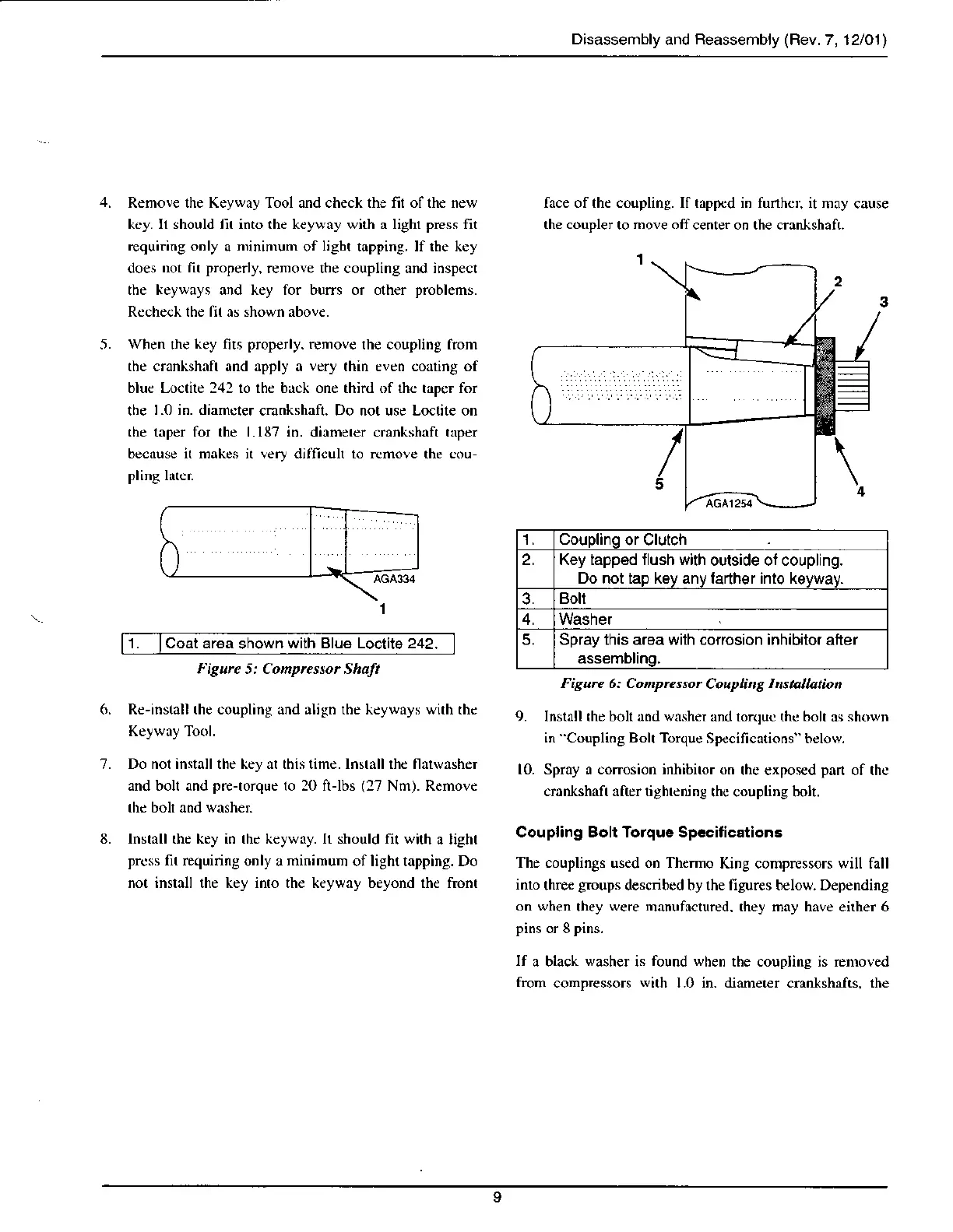
prop€rly. remove
lhe coupling from
the crankshnft and apply a
very
lhin even corting of
bluc Lo€lite 242 to the brck one third of the tapcr for
the
I.0 in. diamcter
cmnkshaft. Do not use Lo€tile on
the taper fbr the Ll87 in. diamerer crankshnft trper
becruse it makes it lery dilficuh 10 remole thc cou-
plinS latcr
1.
lCoat
area
shown
with Blu€ Loctita 242.
face of lhe coupling. If tapFd in funhcr, it
nay cause
the coupler
to
nove off
center on the crar ishaft.
1. Couplinq
or Clutch
2. Key tapped flush with
outside ot coupling.
Do not tap key any larth€r into keyway.
3.
Boll
4.
5. Spray this area with corrosion inhibitor
after
assembling,
l isutc s: Conpressor Shalt
Rc-ins(all the coupling and rlign the keyways with thc
Keyway Tool.
Do nor installthe key fl this time. lnsrall rhe fl w,Nher
and bolr and
pre-rorque
ro 20 ft-lbs
(27
Nrn). Renove
lnstrll the key in rhc keywry. Ir should fil with
a light
prcss fit requiring
only a
ninimum
oflight tapping. Do
not inslall the key inro the keyway beyond the fronr
Fisure 6: Conprcssor
Coupling
Instauation
9. Instrll the bolt nnd wnshe.
and lorquc thc
bolt
as
shown
in
Coupling
Bolt Torque
Sp€cifications" below.
10. Spray a conosion inhibitor on
the €xposed
pan
of thc
.mnl,shxfr :rfrrr ri8hrcnjng rh(
(oupling
hoh.
Coupling Boll Toiquc Spccitications
The couplings used on Themo
King compressors will fall
into
three
groups
described by the figures below. Depending
on wh€n
they
were
manufactured. they may have either 6
pins
or 8
pins.
If
a black
washer
is
found when
the coupling is removed
frorn
compressors
with
1.0 in. diameter crankshafts. the