Disassembly and Reassembly
(Rev.
7. 12l01)
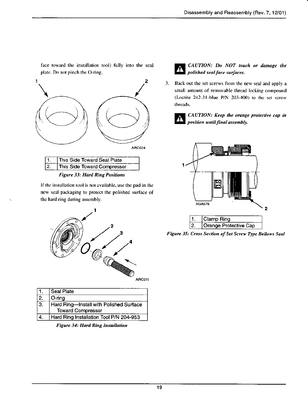
fa€e toward thc instrllrtion t@l)
plarc. Do not pinch
the O-ring.
fully inb
thc seal CAUTION: Do NOT touch
or danage the
potkhed
seat
face
su.Ioces.
l. Bnck out the sel screws from the
new serl and apply n
smrll anoum of removable
thread locking conpound
(Loctile
242
3l blue P/N 103-.{}0) to thc sct sqcw
CAUTION: Kecp th" orung? protectiee
cap in
position
un.il
lnal
asscnbry.
1 Th
s Side Toward Seal Plate
2. tn
s Side Toward Comoressor
Figure 33: Ha.d Rins Positions
If thc instauation
toolis nor.rvail$le, use the
pad
in fte
new scal
pnckaging
to
protect
the
polished
surface
of
rhc hrrd ring dunng
$scmbly.
,tt
'ok'
Seal Plate
2. O-dng
3. Hard Ring-lnstall with Polished
Surtace
Toward Comoressor
4. Hard Rinq Installation Tool P/N
204-953
Figure 31: Hard Ring Instalhtion
l Clamp Ring
2. Orange Proleclive
Cap
Figun 35: Cross Section
ofSe. Scre|'Type Beuoes Seal
19