Do you have a question about the Thermo Scientific 146i and is the answer not in the manual?
Explains how the calibrator works, including dilution, ozone generation, GPT, permeation oven, and photometer principles.
Lists technical specifications for gas dilution, permeation oven, ozone generator, photometer, and remote operation.
Details how to unpack the instrument, check for shipping damage, and inspect internal components.
Guides through connecting zero air, gas cylinders, and installing the permeation tube if the option is present.
Explains how to use the rear panel I/O connector for remote control of flow modes, ozone levels, and gas settings.
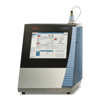
Illustrates the menu-driven software, including Power-Up, Run, and Main Menu screens.
Lists submenus for instrument parameters and settings, accessible from the Run screen.
Allows setting operational modes like Standby, Gas Dilution, Permeation Oven, O3, and Photometer via an intuitive menu.
Details the procedure for calibrating mass flow controllers using a NIST traceable flow meter.
Describes calibrating the ozone generator using a primary standard or analyzer.
Explains how to perform an ozonator control check by connecting to a Model 49i PS and comparing readings.
Read safety precautions before beginning any procedures in this chapter.
Provides procedures to inspect and clean the fan filter by removing guards and flushing.
Explains how to monitor detector frequencies and noise using the Intensity Check menu.
Addresses capillaries (Ozonator, Photometer, Pressure Gauge, Pump) and procedures for inspection and cleaning if blocked.
Provides general troubleshooting information and checks to perform for instrument problems.
Illustrates board-level connections for common electronics and measurement systems for troubleshooting.
Lists connector pin descriptions for various boards, used with connection diagrams for troubleshooting.
Read safety precautions before beginning any procedures, noting service procedures are for qualified representatives.
Lists replacement parts for major subassemblies and indicates component locations.
Provides the procedure to replace the fuse, specifying fuse types and voltage ratings.
Details procedures to check for leaks in the system and leak test the pump, with options for photometer presence.
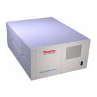
Describes the Model 146i analyzer components, including flow system, photometer, and solenoids.
Provides an overview of the software structure, organizing tasks into instrument control, monitoring, calculations, and communication.
Details system boards, assemblies, and connectors, including motherboard and measurement interface board.
Describes input/output functions and components, covering analog/digital outputs, inputs, and serial ports.
Provides zero, precision, and span checks; ozone level depends on light intensity and gas flow.
Maintains stable oven temperature for gas flow, mixing oven stream with bypass flow using back pressure regulator.
Describes calibrating the permeation tube oven temperature indicator and using permeation tubes.
Describes how to send commands remotely in the instrument's remote mode, including command format and error handling.
Provides commands for reporting and setting photometer averaging time, gas concentration, and flow controller data.
Lists commands for reporting and setting alarm conditions for temperatures, concentration, and intensity.
Covers commands for clearing records, setting logging periods, and reporting list of selections for records and streaming data.
Defines communication parameters for serial port configuration, including data bits, stop bits, parity, and baud rate.
Describes supported function codes like Read Coils, Read Inputs, Read Holding Registers, and Force Single Coil.
Lists MODBUS commands supported for the Model 146i, including Coil Numbers and Register Variables.
| Linearity | ±1% of full scale |
|---|---|
| Operating Temperature | 15 to 35 °C |
| Power Requirements | 100-240 VAC, 50/60 Hz |
| Zero Drift | <1 ppb/24 hours |
| Span Drift | < 1% of full scale/24 hours |