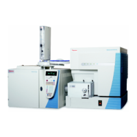
Do you have a question about the Thermo Scientific TRACE 1600 and is the answer not in the manual?
Information regarding safety precautions and warnings for instrument operation.
Details on compliance with electromagnetic compatibility standards.
Guidance on following precautionary notices and understanding safety symbols and signal words.
Explanation of WARNING and CAUTION signal words and associated safety symbols.
Guidelines for safely connecting hydrogen to the system, covering piping, fittings, and valves.
Guidelines for purchasing hydrogen, recommending generators and proper use.
Guidelines for storing compressed hydrogen gas and cryogenic liquid hydrogen safely.
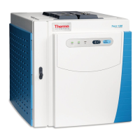
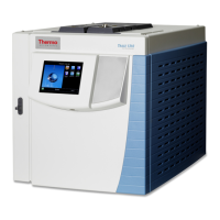
Instructions for correctly placing the TRACE 1600/1610 instrument on a workbench.
Procedures for installing front/back injector and detector modules into their respective housings.
Instructions for connecting gas supply lines to the GC gas inlets using proper fittings.
Procedure to test gas supply lines for leaks after connecting them to the GC.
Instructions for connecting a coolant supply (CO2 or N2) to the GC's cryogenic cooling option.
Instructions for connecting a coolant supply for PTV/PTVBKF injectors with cryogenic cooling.
Instructions for opening the duct to introduce the transfer line inner tube into the GC oven for MS coupling.
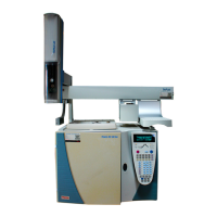
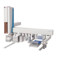
Instructions for installing and connecting TriPlus RSH, TriPlus 100 Liquid Sampler, or AI/AS 1610 autosamplers.
Steps for installing the Chromeleon and SII for Xcalibur data systems software on a PC.
Instructions for connecting the GC and external modules to the power supply.
Procedures for setting the desired IP address and LAN communication port for the GC.
Guidelines for positioning and connecting capillary columns within the GC oven.
Instructions for installing a capillary column, connecting it, and performing initial conditioning.
Important safety and operational notes before performing routine maintenance.
List of necessary supplies and tools for performing routine maintenance on the GC.
Step-by-step instructions for powering on the GC instrument.
Procedure for safely shutting down the GC instrument.
Instructions for cleaning the exterior of the GC instrument to remove dirt and debris.
Procedure for replacing the GC column when performance degrades or troubleshooting indicates maintenance.
Instructions for maintaining the Instant Connect Split/Splitless injector (SSL).
Procedures for maintaining the SSLBKF injector for backflush applications.
Instructions for maintaining the Instant Connect Gas Sampling Valve injector (GSV).
Procedures for maintaining the Instant Connect Helium Saver Injector Module (HeS-S/SL).
Instructions for maintaining the Instant Connect Programmable Temperature Vaporizing injector (PTV).
Procedures for maintaining the PTVBKF injector for backflush applications.
Instructions for maintaining the Instant Connect Flame Ionization Detector (FID).
Procedures for maintaining the Instant Connect Nitrogen Phosphorous Detector (NPD).
Instructions for maintaining the Instant Connect Thermal Conductivity Detector (TCD).
Procedures for maintaining the Instant Connect Electron Capture Detector (ECD).
Instructions for maintaining the Instant Connect Flame Photometric Detector (FPD).
Information on maintenance for the Pulsed Discharge Detector (PDD).
Instructions for removing and replacing the GC's top cover to access internal compartments.
Procedure for removing and replacing the GC's left side panel.
Instructions for removing and replacing the GC's right side panel.
Procedure for removing and replacing the GC's back cover for accessing rear compartments.
Instructions for removing and replacing the GC's front door cover.
Procedures for removing and replacing the instrument's Electronic Module.
Instructions for replacing the complete oven heater baffle assembly.
Procedure for replacing the oven heater temperature sensor.
Instructions for replacing the oven motor, requiring removal of several parts.
Procedure for replacing the oven flap motor and cooling duct assembly.
Procedure to remove contaminants from SSL, SSLBKF, HeS-S/SL, PTV, PTVBKF injectors.
Instructions for removing/replacing a front/back injector module.
Procedures for cleaning the SSL injector body.
Procedures for cleaning the PTV injector head assembly.
Procedures for cleaning the PTVBKF injector head assembly.
Instructions for removing/replacing a front/back detector module.
Instructions for maintaining the Instant Connect Flame Ionization Detector (FID).
Procedures for maintaining the Instant Connect Nitrogen Phosphorous Detector (NPD).
Instructions for maintaining the Instant Connect Thermal Conductivity Detector (TCD).
Procedures for maintaining the Instant Connect Electron Capture Detector (ECD).
Instructions for maintaining the Instant Connect Flame Photometric Detector (FPD).
Instructions for installing the optional oven exhaust kit to vent hot air away from the working area.
Procedures for installing the Merlin Microseal High Pressure Valve kit on specific injectors.
Instructions for installing the Purge & Trap Adapter kit for use with a Purge & Trap system.
Procedures for installing adapters for connecting metal packed columns to injectors and detectors.
Instructions for installing the HS Adapter kit for use with a TriPlus 300 Headspace sampling system.
Procedures for installing the Large Volume Splitless kit for introducing large liquid samples.
Instructions for connecting SSLBKF/PTVBKF injector modules with precolumn and capillary column.
Procedures for connecting SSLBKF/PTVBKF injectors with precolumn and capillary column for high temperature applications.
Instructions for installing the NoVent Microfluidics on TRACE GC and mass spectrometer.
Procedures for installing the FTIR Make-up module for connection with FT-IR Spectrometer.
Instructions for installing the Hot Injection Adapter kit for use with external gas sampling devices.
Instructions for performing Dual FPD configuration by connecting a second photomultiplier tube.
Instructions for installing a kit to adjust carrier gas pressure for GSV injector.
Procedures for installing the support kit for packed columns into the GC oven.
Instructions for installing the ECD Exhaust Vent Kit to vent exhaust gases to a fume hood.
Instructions for adding front/back SSL, SSLBKF, PTV, or PTVBKF injector modules.
Procedures for adding front/back Gas Sampling Valve injector modules.
Instructions for adding front/back FID, TCD/TCD In-Series, ECD, or FPD detector modules.
Procedures for adding front/back NPD detector modules.
Instructions for updating the GC with the Aux Temperature/Cryo module.
Procedures for installing the Instant Connect Helium Saver Injector Module (HeS-S/SL).
Instructions for adding front/back PDD detector modules.
Procedures for installing detector and control modules of the Generic Detector Interface.
Instructions for installing the Analog Output Interface (AOI) on the GC.
Instructions for installing and configuring the Oven Cryo system on TRACE 1600/1610.
Procedures for installing and configuring PTV/PTVBKF Cryo system on TRACE 1600/1610.
Instructions for updating TRACE 1600/1610 with the Auxiliary Gas System.
Instructions for updating TRACE 1600/1610 with the hydrogen sensor.
Instructions for upgrading a TRACE 1600 GC to a TRACE 1610 GC.
Procedures for updating TRACE 1600/1610 stand alone to MS version with upgrade kit.
Instructions for updating the TRACE 1610 HMI software using a USB stick.
Guidance on verifying correct power supply and troubleshooting power-on issues.
Steps to verify instrument communication with the computer and software.
Troubleshooting common causes of sensitivity issues like air leaks, contamination, or simple problems.
Information on error messages visualized during GC malfunctioning and how to reset alarms.
Information on how to contact Technical Support, including required details like model and serial number.
| Type | Gas Chromatograph |
|---|---|
| Column | Capillary |
| Oven Temperature Range | Ambient +4 °C to 450 °C |
| Maximum Heating Rate | 120 °C/min |
| Maximum Number of Injectors | 2 |
| Temperature Programming | Yes |
| Detectors | FID, TCD, ECD, NPD, FPD |
| Data System Compatibility | Chromeleon Chromatography Data System (CDS) |
| Autosampler Compatibility | Yes |