20. Check the color of the CO2 sensor. If it is brass-colored, it is a T/C
sensor. If it is white-colored, it is an I/R sensor.
• For replacing the T/C sensor gasket - Remove the two wingnuts
and pull the T/C sensor down. Pull up on the brown connector to
unplug the T/C sensor. Remove the gasket and install the new
sensor gasket. Be sure to use the appropriate gasket from the kit by
matching the center hole diameter. Reconnect the T/C sensor. Note
that the brown connector is keyed. Install the two wingnuts to
secure the CO
2 sensor.
• For replacing the I/R sensor gasket - Remove the two wingnuts and
pull the I/R sensor down. Disconnect the two latches and pull the
I/R sensor off the connector. Remove the gasket and install the new
sensor gasket. Be sure to use the appropriate gasket from the kit by
matching the center hole diameter. Reconnect the I/R sensor. Note
that the connection is polarized. Install the two wingnuts to secure
the CO
2 sensor.
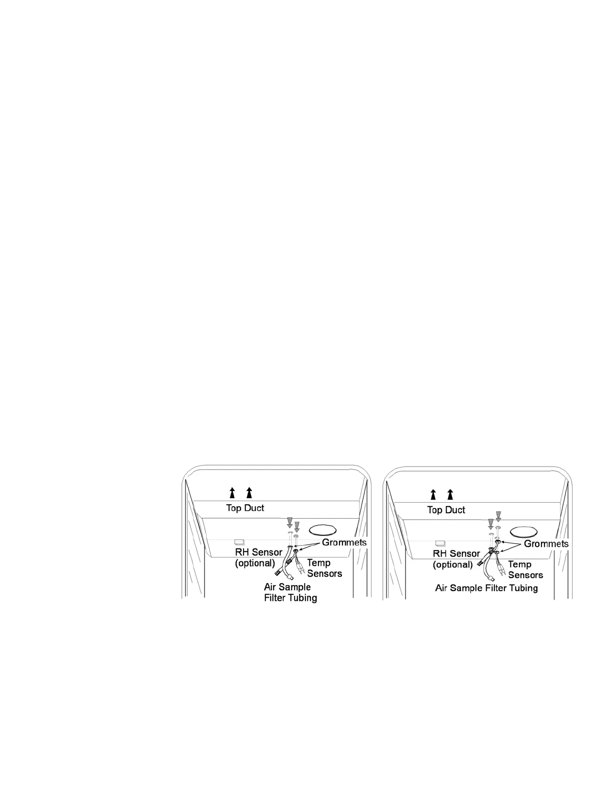
21. Replace the grommets in the top duct with included new ones.
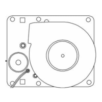
22. Install the top duct by feeding the temperature sensors (plus RH sensor,
if applicable) and air sample filter tubing through the appropriate holes
in the top duct as it is raised to the chamber ceiling. Be careful not to
pull the grommets through the duct. Insert the left side of the top duct
in the left duct sheet opening and locate the mounting studs and
blower scroll into their appropriate holes in the top duct. Then install
the wingnuts to secure the duct. See Figure 14.
12 Preventive Maintenance Kit 2270105
Installation - Release 5,
Series II (continued)
Figure 14. Two Configurations for Assembly
 Loading...