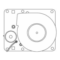
7. Pull down firmly to remove the blower wheel from the motor shaft.
Discard the blower wheel. Slide the new blower wheel with the round
hole up the motor shaft until the wheel is against the shoulder of the
shaft. Make sure the wheel turns freely.
8. Install the scroll using the four screws retained from Step 6.
9. Replace the blower plate gasket by first removing the five wingnuts and
one hex nut. Then disengage the blower plate from the chamber
ceiling. There may be suction build-up on the plate gasket. Remove the
blower plate gasket and install the new one from the kit.
Note Support the blower plate. Do not allow it to hang from the wiring,
especially the temperature sensor.
▲
10. Install the blower plate. When aligning the mounting holes, all wiring
and tubing must be pushed up into the hole behind the plate to
prevent them from becoming cut or pinched. Install the wingnuts and
the hex nut to secure.
11. Install the new air sample filter and tubing onto the fitting located on
the blower plate. See Figure 3.
12. Check the color of the CO
2 sensor. If it is brass-colored, it is a T/C
sensor. If it is white-colored, it is an I/R sensor.
• To replace a T/C sensor gasket, first remove the 2 wingnuts and
pull the sensor down. Then pull up on the brown connector to
unplug the sensor. Remove the gasket and install the new one. Be
sure to use the correct gasket from the kit by matching the center
hole diameter. Reconnect the T/C sensor. Note: The brown
connector is keyed. Secure the CO2 sensor with the 2 wingnuts.
• To replace an I/R sensor gasket, first remove the 2 wingnuts and
pull the sensor down. Then disconnect the 2 latches and pull the
sensor off the connector. Remove the gasket and install the new
one. Be sure to use the correct gasket from the kit by matching the
center hole diameter. Reconnect the I/R sensor. Note that the
connection is polarized. Secure the I/R sensor with the 2 wingnuts.
3Preventive Maintenance Kit 2270105
Installation - Release 1
through 3 (continued)
 Loading...