9Preventive Maintenance Kit 2270105
Note Several parts included in this kit are not used in this application. ▲
1. Remove the shelves and the side duct sheets from
the interior of the unit.
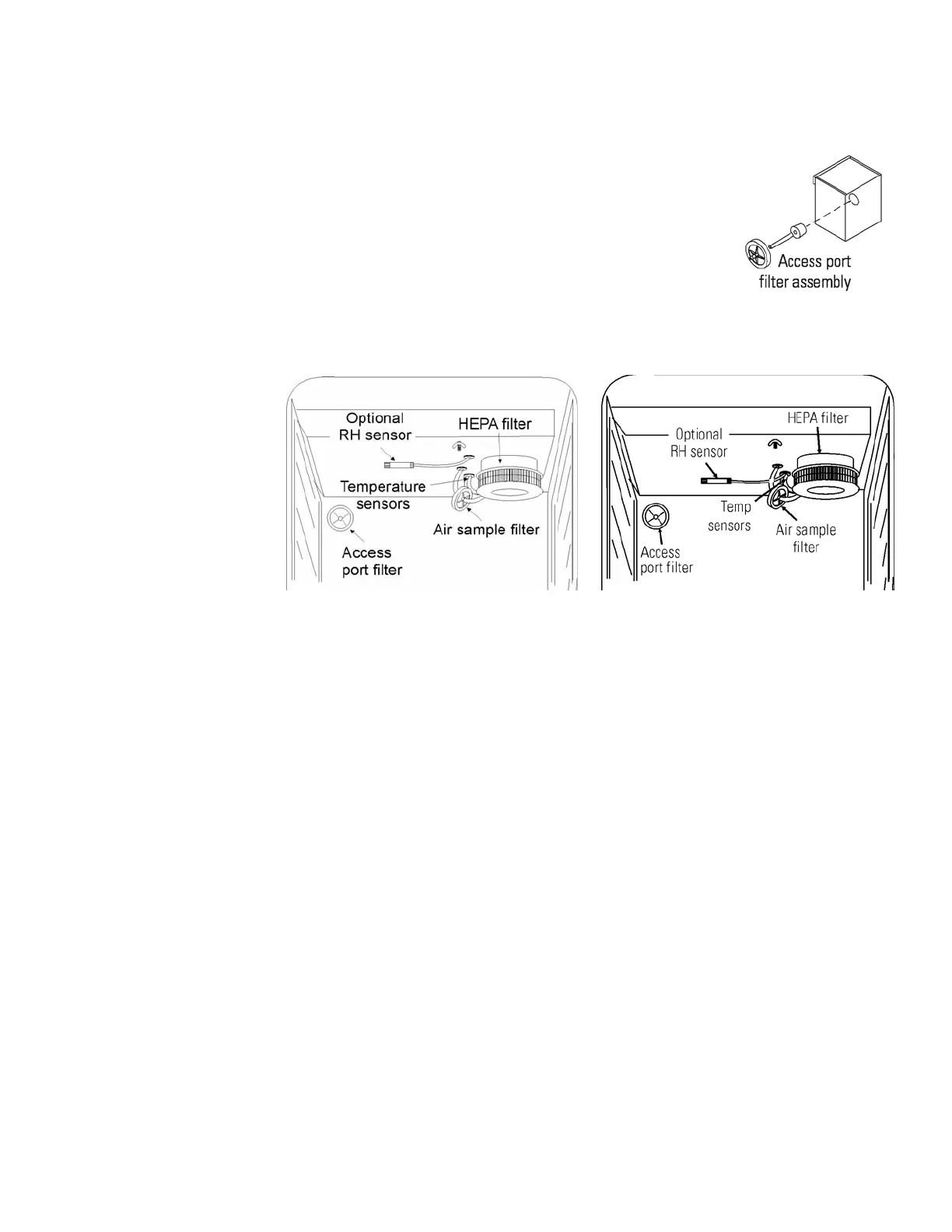
2. Remove and discard the access port filter
assembly. See Figure 9.
3. Remove the temperature sensors and the air
sample tubing from the back of the blower scroll.
See Figure 10.
4. Remove and discard the air sample filter assembly from the fitting on
the blower plate.
5. If the unit is equipped with the optional RH sensor, unfasten it from
the clip on the top duct. See Figure 10.
6. Remove the HEPA filter by pulling it downward. Discard the filter.
7. Remove the wingnuts securing the top duct to the chamber ceiling.
Slide the duct down and off the temperature sensors and air sample
filter tubing (and RH sensor, if applicable).
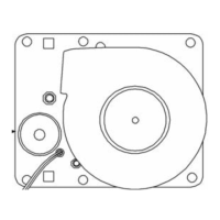
8. Remove the blower scroll by first pushing the black lever clip closest to
you toward the scroll. Then turn the blower scroll to the right to
disengage it from the blower scroll plate. Some manipulation may be
required as alignment holes are keyhole-shaped. See Figure 10.
9. Remove the remaining wingnut, then pull down to remove the blower
wheel from the motor shaft. Discard the blower wheel.
Installation -
Release 5, Series II
Figure 9. Back Corner
of Chamber
Figure 10. Two Configurations
 Loading...