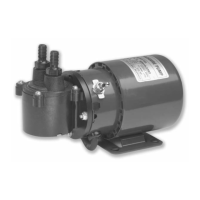
Dionex AXP/AXP-MS Manual
7.2.2 General Information on Inputs
The pump's inputs are on the 10-pin terminal board connector. The
pinout is:
Pin Function
10 VOLTAGE COM
9 VOLTAGE IN
8 FREQ IN
7 ENABLE IN
6 PUMP-RUN
5 PUMP-STOP
4 No connection
3 No connection
2 No connection
1 COM
7.2.3 General Information on Run, Stop, and Enable Inputs
The PUMP-RUN, PUMP-STOP, and ENABLE IN inputs operate from
an internal 5 VDC source. Each input draws approximately 0.008 amp
when connected to COM. To activate the PUMP-RUN, PUMP-STOP,
or ENABLE IN input, connect it to COM. Any device capable of
switching 0.008 amp (including a switch contact, a relay contact, an
open collector output, an open drain output, or any output with a high
logic level output of 3.8 to 6.0 volts and a low logic level output of 0.0
to 0.5 volt) can be connected between the PUMP-RUN, PUMP-STOP,
or ENABLE IN input and COM. A switch contact or a relay contact is
preferred, since this type of connection will provide isolation between
the pump and the controlling device. The COM terminal is internally
connected to the pump's chassis ground and should be connected to the
controlling device's ground or zero volt terminal when the controlling
device has an open collector output, an open drain output, or any
output with logic level output.
7.2.4 Run and Stop Inputs
The pump's
motor can be commanded to run or stop from the rear
panel inputs when the pump’s flow rate is controlled from the front
panel or by the voltage or frequency input. The two modes of
operation for the run and stop inputs are described below:
Dual-Signal Pulse: In this mode of operation, both the PUMP-RUN
and PUMP-STOP inputs are normally at a high logic level. To start the
pump, pulse the PUMP-RUN input to a low logic level for a minimum
of 500 mS. To stop the pump, pulse the PUMP-STOP input to a low
logic level for a minimum of 500 mS.
33
 Loading...