Do you have a question about the Thermo Scientific Dionex and is the answer not in the manual?
Overview of system design, capabilities, and main components (AE, LE, SP, SS).
Describes the structure and content of the operator's manual.
Lists other available manuals and resources for the system.
Covers safety messages, warnings, precautionary statements, and symbols.
Details EMC standards, safety specifications, and EU directives.
Illustrates typical system configurations with various modules.
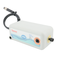
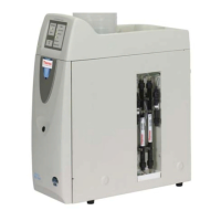
Introduces the SP, its versions (SP1, SP2, generic) and enclosure types.
Details power, USB, leak sensor, and drain port functions.
Covers components (valves, pumps, vessels) and panel configurations.
Details I/O lines, analog inputs, TTL/relay, sensors, and control options.
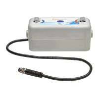
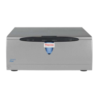
Introduces the SS and its stream selection capabilities.
Covers enclosure types, power, computer connections, and leak sensor.
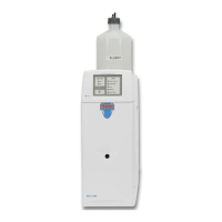
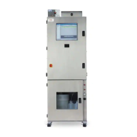
Introduces the AE enclosure and its NEMA environmental ratings.
Details exterior features (Emergency Off) and interior features (shelves, outlets).
Covers power, computer connections, TTL/relay, ventilation, A/C, purge, and tower light.
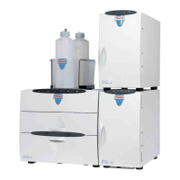
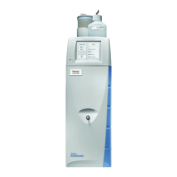
Introduces the LE enclosure and types of containers it accommodates.
Explains the control panel, gas pressure, and pneumatic requirements.
Details tubing and fittings for liquid and gas connections.
Steps for preparing site, connecting facilities, cables, and inlet lines.
Procedures for initial power-on, software setup, and system calibration.
Guides for routine startup, operation monitoring, and checks.
Instructions for short-term and long-term system shutdowns.
Daily checks for gas pressure, reagent supplies, and lines.
Weekly tasks including standard solutions and pump maintenance.
Biweekly tasks for reagent reservoirs and eluent trap columns.
Monthly tasks like replacing in-line filters and guard columns.
Quarterly tasks including pump seals and rotary valve maintenance.
General strategies for isolating and resolving system problems.
Explains error messages, severity levels, and their meanings.
Addresses liquid leaks, leaking fittings, and broken lines.
Discusses detection and resolution of air and gas leaks.
Troubleshoots issues where the system or components do not power up.
Procedure to identify and remove restrictions in the fluid system.
Step-by-step guide for replacing pump check valve cartridges.
Instructions for replacing defective pump check valves.
Procedure for replacing pump piston and backup seals.
Guide for replacing the seal in the waste valve.
Provides instructions to access the SP electronics board.
Steps for replacing solenoid valves on the SP panel.
Adjusting peristaltic pump speed and calibrating system components.
Steps for safely replacing main power fuses for SP or SS.
Operating temperature and humidity ranges for all components.
Electrical and physical specifications for AE and LE enclosures.
Electrical and physical specs for SP/SS, including pumps and valves.
Electrical and physical specifications for the air conditioner/heater.
Provides parts and steps for installing SP TTL and relay control.
Details installing TTL/relay connectors on AE and connecting to SP.
Instructions for connecting wires to breakout boards and installing them.
Steps for mounting the tower light and connecting its cable.
Lists parts and requirements for the AE purge kit installation.
Steps for installing the purge control unit and related components.
Lists parts and requirements for installing a peristaltic pump.
Covers installing pump, cable, tubing, and configuring in Chromeleon.
Lists parts and requirements for installing liquid level sensors.
Steps for attaching the sensor to containers and connecting the cable.
Details parts and steps for installing the thermal control board.
Steps for mounting the vial cooler and connecting its cable.
Procedures for connecting and installing the heated dilution vessel.
Steps for notifying, turning off power, and installing lockout devices.
| Category | Analytical Instruments |
|---|---|
| Brand | Thermo Scientific |
| Manufacturer | Thermo Fisher Scientific |
| Product Line | Dionex |
| Detector Types | Conductivity, Electrochemical, UV-Vis |
| Software | Chromeleon |
| Compliance | 21 CFR Part 11 |
| Column Types | Ion Exchange |