Do you have a question about the Thermo Scientific Dionex AXP and is the answer not in the manual?
Details compliance with safety and EMC standards for the pump.
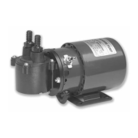
Provides an overview of the pump's design, features, and wetted materials.
Lists technical specifications like flow rates, pressure, dimensions, and power.
Instructions for inspecting the pump upon arrival and checking contents.
Recommended environmental conditions and placement for the pump.
Guidance on connecting the pump to a power source safely.
Discusses preventing pumping problems by preparing solvents, including outgassing, cavitation, filtration, and compatibility.
Covers mobile phase reservoirs, self-flush solution, and tubing connections for instrument setup.
Details procedures for flushing the pump with isopropanol and packaging for transport.
Explains the digital display, keypad functions, and status LEDs on the pump's front panel.
Details the RS-232C port for controlling the pump remotely via a PC.
Explains the liquid system flow path, pump cycle, and pulse damping mechanism.
Covers microprocessor control, DC power supply, and motor stall detection.
Instructions for checking and replacing inlet filters to prevent cavitation and flow loss.
Covers removing the pump head, replacing piston seals, and cleaning the pump head assembly.
Procedures for cleaning or replacing check valves to resolve flow issues caused by particles.
States that the pump has no lubrication requirements as bearings are permanently lubricated.
Details the location and replacement procedure for fuses protecting the pump's power and DC supplies.
Instructions for replacing the battery that powers the pump configuration memory.
Lists part numbers for PEEK/Bioclean check valve kits and tubing.
Lists part number for the piston seal kit.
Lists various general replacement parts including loops, filters, cables, and fuses.
Details the RS-232C port, pinout, and PC connection for serial communication.
Describes terminal board connectors for remote control via logic levels, voltage, or frequency.
Explains output signals for pressure faults and motor stalls on the 6-pin connector.
Details the pinout for the 10-pin terminal board connector for various inputs.
Explains how PUMP-RUN, PUMP-STOP, and ENABLE IN inputs operate using logic levels.
Describes dual-signal pulse and single-signal level modes for controlling pump run and stop states.
Explains how the ENABLE IN input disables front panel control and enables rear panel control.
Details how to select remote operation modes controlled by voltage or frequency inputs.
Describes remote flow control using a 0-10 VDC input signal and preventing ground loop issues.
Details remote flow control using a 0-10,000 Hz input frequency signal.
| Flow Rate Range | 0.001 to 10.0 mL/min |
|---|---|
| Flow Rate Precision | <0.1% RSD |
| Pressure Range | 0 to 5000 psi |
| Power Supply | 100-240 V, 50/60 Hz |
| Gradient Composition Accuracy | ±0.5% |