Do you have a question about the Thermo Scientific Dionex ICS-1000 and is the answer not in the manual?
This document outlines the preventive maintenance procedure for the Dionex ICS-1000, ICS-1100, ICS-1500, ICS-1600, ICS-2000, and ICS-2100 Ion Chromatography Systems. Thermo Fisher Scientific recommends performing this procedure annually, as well as before scheduled Performance Qualification tests, to ensure optimal system performance and longevity.
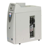
The Dionex ICS series of Ion Chromatography Systems are designed for the separation and detection of ions in various samples. These systems typically consist of a pump, an injection valve, separation columns, a detector, and a data acquisition system. The pump delivers the eluent (mobile phase) through the system at a controlled flow rate. The injection valve introduces the sample into the eluent stream. The separation columns then separate the ions based on their interactions with the stationary phase. Finally, the detector measures the separated ions, and the data acquisition system processes and displays the results. The preventive maintenance procedure focuses on critical components that ensure the accurate and reliable operation of the pump and injection system, which are fundamental to the overall function of the ion chromatograph.
The Dionex ICS systems are designed for ease of use and reliability in laboratory settings. The systems feature accessible components for maintenance and troubleshooting. The control panel and touch screen PUMP page allow users to manage system operations, including opening and closing eluent valves and priming the pump. The use of Chromeleon Chromatography Data System further enhances user interaction by providing a comprehensive platform for system control, data acquisition, and analysis. The design emphasizes clear labeling of ports and components, such as the injection valve plumbing diagrams (Figure 1 and Figure 2), to guide users during setup and maintenance. The system also incorporates features like magnetic retention for the piston, simplifying its reinstallation. The importance of proper fitting tightening is highlighted to prevent damage and ensure system integrity, indicating a user-friendly design that also emphasizes careful handling.
The preventive maintenance procedure is comprehensive, covering several key components to ensure the long-term performance of the Dionex ICS systems. The procedure is designed to be performed by users with appropriate training and includes detailed, step-by-step instructions.
This is a critical step that involves replacing the rotor seal, isolation seal, and stator face of the injection valve. The injection valve is responsible for accurately introducing the sample into the system. Over time, these seals can wear out, leading to leaks or inaccurate sample delivery. The procedure requires turning off the pump, disconnecting liquid lines, and following instructions provided in the Injection Valve Rebuild Kit (P/N 057896). Diagrams (Figure 1 and Figure 2) are provided to assist with reconnecting the liquid lines correctly. This maintenance ensures precise sample injection and prevents sample loss or contamination.
If an auxiliary valve is installed and has been used extensively, it may also require rebuilding. Similar to the injection valve, the auxiliary valve's seals can degrade, affecting its performance. The procedure references the basic steps for rebuilding the injection valve, using either an Injection Valve Rebuild Kit (P/N 057896) for a 6-port valve or a 10-port Valve Rebuild Kit (P/N AAA-061759) for a 10-port valve. This optional step ensures the integrity of additional valving in the system.
The pump check valves are essential for maintaining consistent flow and pressure within the system. Worn or faulty check valves can lead to flow pulsations, pressure instability, and poor chromatographic results. The maintenance involves rinsing the pump flow path, closing the eluent valve, and turning off the pump. Users are instructed to wear cleanroom gloves to prevent contamination. The procedure details disconnecting tube fittings, loosening and removing the old check valve assemblies using a 1/2-inch wrench (P/N 062336), and installing new check valve cartridges (P/N 045994) into their respective housings (Figure 4). Specific attention is given to the correct orientation of the cartridges and proper tightening to avoid damage to the pump head. Figure 3 illustrates the location of the check valves on the pump head.
These seals are crucial for preventing leaks and maintaining the efficiency of the pump. The piston rinse seal prevents eluent from leaking past the piston, while the piston seal ensures proper compression and delivery of the eluent. The procedure involves removing the pump head and piston, which requires careful handling to avoid breaking the piston (Figure 5 and Figure 6). Instructions are provided for removing the old piston rinse seal and O-ring, and then installing new ones (P/N 048722 for the rinse seal, P/N 059283 and P/N 014895 for O-rings). Special care is advised when handling the soft plastic piston rinse seal to prevent nicks or gouges that could lead to leaks (Figure 7). The process also includes removing the old piston seal by hydraulic unseating and installing a new one (P/N 055870), with an option to lubricate with isopropyl alcohol for easier insertion. Reinstalling the head and piston as a single assembly is recommended to ensure proper centering of the piston onto the magnetic follower.
The O-rings in the waste and priming valves are vital for sealing these components and preventing leaks during pump operation and priming. The procedure involves turning the valve knob counterclockwise to loosen and remove the valve from the pump head (Figure 8). Users are instructed to carefully extract the old O-ring (P/N 055752) and replace it with a new one (Figure 9), taking care not to scratch the cavity, as this could cause leaks. Reinstalling the valve and tightening it fingertight completes this step.
The end-line filter prevents particulate matter from entering the pump and other sensitive components of the system. Regular replacement is essential to maintain clean flow paths and prevent blockages. The procedure involves installing a new end-line filter (P/N 045987) on the eluent or deionized water line inside the reservoir, ensuring it extends to the bottom and is submerged in liquid to prevent air from being drawn into the system. The document notes that the filter should be changed weekly in continuous operation or whenever it becomes discolored, and more often if bacterial buildup is visible.
This final section outlines the steps to bring the system back online after maintenance. It includes reconnecting all liquid lines, power cord, turning on the system, opening the eluent valve, and priming the pump. Crucially, it emphasizes checking for leaks from check valves and fittings and tightening them as needed. The procedure concludes with recording the date for the next preventive maintenance on the provided label (P/N 062823) and completing the Preventive Maintenance Checklist.
The document stresses the importance of using cleanroom gloves to prevent contamination of pump parts during disassembly. It also includes an "IMPORTANT" note about not overtightening fittings, especially split-cone ferrules, to prevent damage and tubing restriction. The use of ASTM filtered, Type I (18 megohm-cm) deionized water is specified for rinsing and other procedures. A Preventive Maintenance Checklist (Section 8) is provided to help users track completed steps and verify that maintenance is performed at scheduled intervals. The estimated time required for the entire procedure is 30 to 45 minutes.
Overall, the preventive maintenance procedure for the Dionex ICS systems is designed to be thorough, ensuring that critical components are regularly inspected and replaced, thereby extending the lifespan of the instrument and maintaining its high performance and reliability for ion chromatography applications.
| Type | Ion Chromatography System |
|---|---|
| Detection Method | Conductivity |
| Pump Type | Dual-piston, serial |
| Sample Introduction | Manual or Autosampler |
| Data System | Chromeleon Chromatography Data System |
| Injection Volume | 1 to 100 µL |
| Power Requirements | 100-240 V, 50/60 Hz |
| Eluent Generation | Optional |
| Pressure Range | 0 to 3500 psi (24.1 MPa) |
| Conductivity Detection Range | 0 to 15000 µS/cm |
| Weight | 25 kg |