Do you have a question about the Thermo Scientific Dionex ICS-2000 and is the answer not in the manual?
Explains the fundamentals of Ion Chromatography and the ICS-2000 system's role.
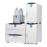
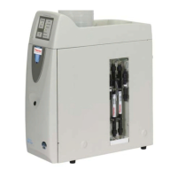
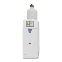
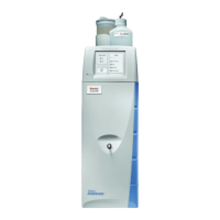
Describes the integrated components and operational modes of the ICS-2000 system.
Explains the manual's structure, including hypertext links and cross-references.
Details the types of safety messages and icons used to convey hazard information.
Explains the meaning of safety symbols found on the ICS-2000 instrument.
Covers the instrument's operational aspects, including front panel, top cover, component panel, and rear panel.
Introduces the Chromeleon software interface for instrument control and data management.
Illustrates the liquid flow paths for different eluent generation configurations.
Provides detailed descriptions of key system components like the pump, detector, and generator.
Outlines the basic steps for routine operation and sample processing.
Guides the user through turning on the instrument and associated components.
Explains how to launch and start the Chromeleon software for instrument control.
Details the steps for preparing, connecting, and setting the eluent reservoir.
Provides step-by-step instructions for priming the pump and eluent lines.
Describes the process for system equilibration and checking operational status.
Offers guidance on sample collection, storage, pretreatment, and dilution.
Describes methods for loading samples via syringe or autosampler and injecting them.
Covers procedures for manual sample processing and automatic batch processing.
Outlines routine maintenance tasks that users can perform on the instrument.
Explains error messages, their icons, severity levels, and general system responses.
Provides specific troubleshooting steps for various error messages encountered.
Addresses common causes and solutions for liquid leaks in system components.
Troubleshoots issues related to pump priming and loss of prime.
Covers troubleshooting steps when the pump fails to start or power on.
Provides solutions for situations where no eluent flow is detected.
Addresses problems causing unstable flow or pressure readings from the pump.
Explains how to troubleshoot and resolve high system backpressure issues.
Describes the phenomenon of ghost peaks and identifies potential causes.
Addresses issues leading to inconsistent peak height or retention time.
Troubleshoots problems affecting retention time and separation selectivity.
Provides steps to take when the conductivity cell shows no signal response.
Explains potential causes and solutions for high cell output readings.
Addresses troubleshooting for unstable or drifting baselines in the chromatogram.
Provides steps to resolve issues when the vacuum degas assembly fails to operate.
Describes how to perform diagnostic routines and calibration procedures.
Details how to locate and resolve restrictions within the system's liquid plumbing.
Provides instructions for the proper replacement of tubing and fittings.
Details the procedure for rebuilding the injection valve, including seal replacement.
Explains how to clean and replace the pump's check valves.
Guides the user through replacing the pump piston seals and rinse seals.
Describes the procedure for replacing a pump piston.
Details the procedure for replacing O-rings in the waste or priming valves.
Explains the steps for safely removing and replacing the conductivity cell.
Guides the user through the process of replacing the suppressor module.
Describes the procedure for replacing the column heater assembly.
Explains how to replace the eluent valve, including preventing eluent leaks.
Guides the user through replacing the leak sensor.
Details the procedure for replacing the EluGen cartridge.
Provides instructions for replacing the Continuously Regenerated Trap Column.
Explains how to replace the EPM Electrolytic pH Modifier.
Guides the user through replacing the EGC CO3 Mixer.
Details the procedure for replacing the EGC holder and degas assembly.
Covers the instrument's main power and fuse specifications.
Lists the physical dimensions, weight, and decibel level of the ICS-2000.
Details the operating temperature, humidity, and pressure requirements.
Describes the specifications of the front panel components, including the LCD touch screen.
Lists the pump's specifications, including type, flow rate, accuracy, and pressure limits.
Covers the detector's specifications, range, temperature compensation, and linearity.
Details the specifications of the conductivity cell, including body material and active volume.
Lists the specifications for the injection valve, including type and wetted components.
Provides specifications for the vacuum degas assembly's channel, pump, and materials.
Lists the operating temperature specifications for the column heater.
Details the eluent generator's concentration ranges based on cartridge type and configuration.
Outlines the necessary environmental, power, and physical installation site requirements.
Guides the user through the process of safely unpacking the ICS-2000 system from its shipping container.
Provides step-by-step instructions for installing the Chromeleon software on the control computer.
Details the procedure for installing the software license using a dongle or license server.
Explains how to establish communication between the ICS-2000 and the control PC via USB.
Guides the user through safely connecting the instrument's power cord to a grounded source.
Details the procedure for powering on the computer and the ICS-2000 instrument.
Covers the initial configuration of Chromeleon, including timebase setup and device assignment.
Provides installation and plumbing instructions for the chromatography columns and suppressor.
Describes how to connect the system's waste lines to a waste container.
Guides the user through the steps for setting up the eluent reservoir.
Explains how to enter the eluent volume for accurate monitoring of eluent usage.
Details the two-part procedure for priming the pump and eluent lines.
Covers the setup procedure for the Eluent Generator, including cartridge installation and conditioning.
Guides the user on creating sample sequences and using application templates in Chromeleon.
Describes the process of equilibrating the system and verifying pressure stability.
Guides the user on checking the system's operational status after equilibration.
Covers the connection and Chromeleon setup for AS or AS50 autosamplers.
Details the connection procedure for the AS40 automated sampler.
Describes how to connect the analog output to external data acquisition devices.
Explains the optional procedure for pressurizing the eluent reservoir with gas.
Explains how to set up the pump's continuous seal wash system.
Describes how to manually connect the ICS-2000 to a control panel without using templates.
Provides solutions for common problems encountered during instrument installation.
Explains basic touch screen interaction, navigation, and button functions.
Describes how touch screen control interacts with Chromeleon's remote mode.
Illustrates the organization and hierarchy of the ICS-2000 touch screen pages.
Details the controls and information displayed on the Home page for daily operation.
Describes the real-time plot display for detector output and its available controls.
Explains the Status page for viewing current operating parameters and eluent level.
Details pump operation settings like pressure limits and degas, and eluent valve control.
Covers settings for the Eluent Generator, including concentration, serial numbers, and cartridge life.
Details settings for the suppressor type, current setting, and automatic power control.
Covers detector settings such as data rise time, conductivity polarity, and analog output.
Displays system version numbers, serial numbers, and installed options.
Allows configuration of touch screen display settings and conductivity display format.
Provides control for the instrument's TTL inputs and relay outputs.
Explains how to access diagnostic and calibration functions via the touch screen.
Describes the TTL/relay connector pin assignments and basic connection steps.
Details how to control external devices using the instrument's TTL and relay outputs.
Provides an example setup for operating the system without Chromeleon software.
Provides instructions for connecting autosamplers to the ICS-2000 system.
Addresses common causes for shifting retention times and points to troubleshooting sections.
Explains how the system indicates when an EluGen cartridge needs replacement.
Lists potential reasons for high conductivity readings, such as suppressor or cell calibration issues.
| Brand | Thermo Scientific |
|---|---|
| Model | Dionex ICS-2000 |
| Category | Laboratory Equipment |
| Language | English |