Section 3 - Installation
3.1 Location
Locate the cabinet on a firm, level surface in an area of
minimum temperature changes. The cabinet should be placed
away from disruptive air currents caused by excessive person-
nel traffic, air-conditioning or heating ductwork, or laboratory
windows and doors. Proper cabinet location is important, as
drafts disrupt critical airflow characteristics and allow room
contaminants to enter or escape the cabinet work area.
Where space permits, fourteen inches should be allowed on
each side of the cabinet for maintenance. A twelve-inch height
should be available from the top of the cabinet to the ceiling.
Place a bubble-type level on the work surface. Adjust the
leveling feet until the cabinet is level and the most comfortable
working height is achieved. Ensure that all four leveling feet
are fully flush against the floor to prevent vibration.
Model 1284/1285 weighs 735 lbs. Model 1286/
1287 weighs 940 lbs. Have sufficient personnel to
lift it.
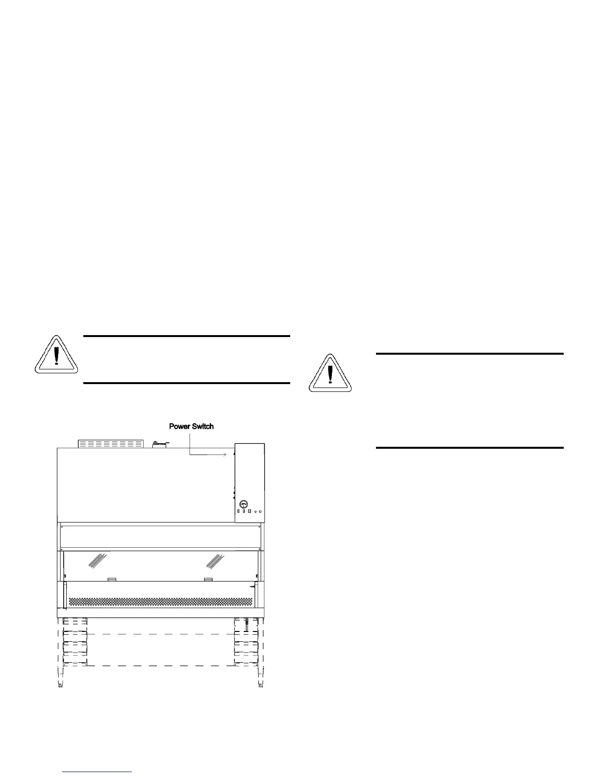
3.2 Power Connection
The power switch is located on the left side of the control
panel (Figure 3 - 1). The power switch is also a circuit breaker
that protects the unit. The electrical wall outlet leading to the
cabinet should be accessible for electrical testing.
This cabinet is equipped with one power cord supplying
power to the blower, lights and receptacles. The cord should be
plugged into a grounded, dedicated circuit. Refer to Section 11
- Specifications or to the serial plate on the front of the unit for
electrical specifications. With the power switch turned off, plug
the line cord into the wall outlet.
3.3 Plumbing Connection
Models 1284 and 1285 have one standard service valve
located on the right side of the work station. Models 1286 and
1287 have two standard service valves located on the right and
left side of the work station. All service valves are piped within
the cabinet. External connection is a 3/8” FPT coupling.
Identification index buttons are supplied. Each cabinet can
accommodate a total four service valves.
Explosive/flammable substances should
never be used in the cabinet, unless approved
and monitored by a biological safety officer
or other qualified individual. However, if
flammable gas is used, emergency shut-off
valves must be located in an accessible area
external to the cabinet.
a. Universal Plumbing Option
The Universal Plumbing option is factory installed.
External connection (1/4” NPT) to the unit is available on the
top and the underside of the cabinet, as well as the standard
side connection. See Figure 3-2.
Class II, A2 Biological Safety Cabinets_______________________________________________________________Installation
3 - 1
Figure 3 - 1