WWW. WWW. WWW. WWW. WWW. WWW.
If you would like to know more about our products or services,
you can view our complete range online, WWW.THERMOGROUPUK.COM
5
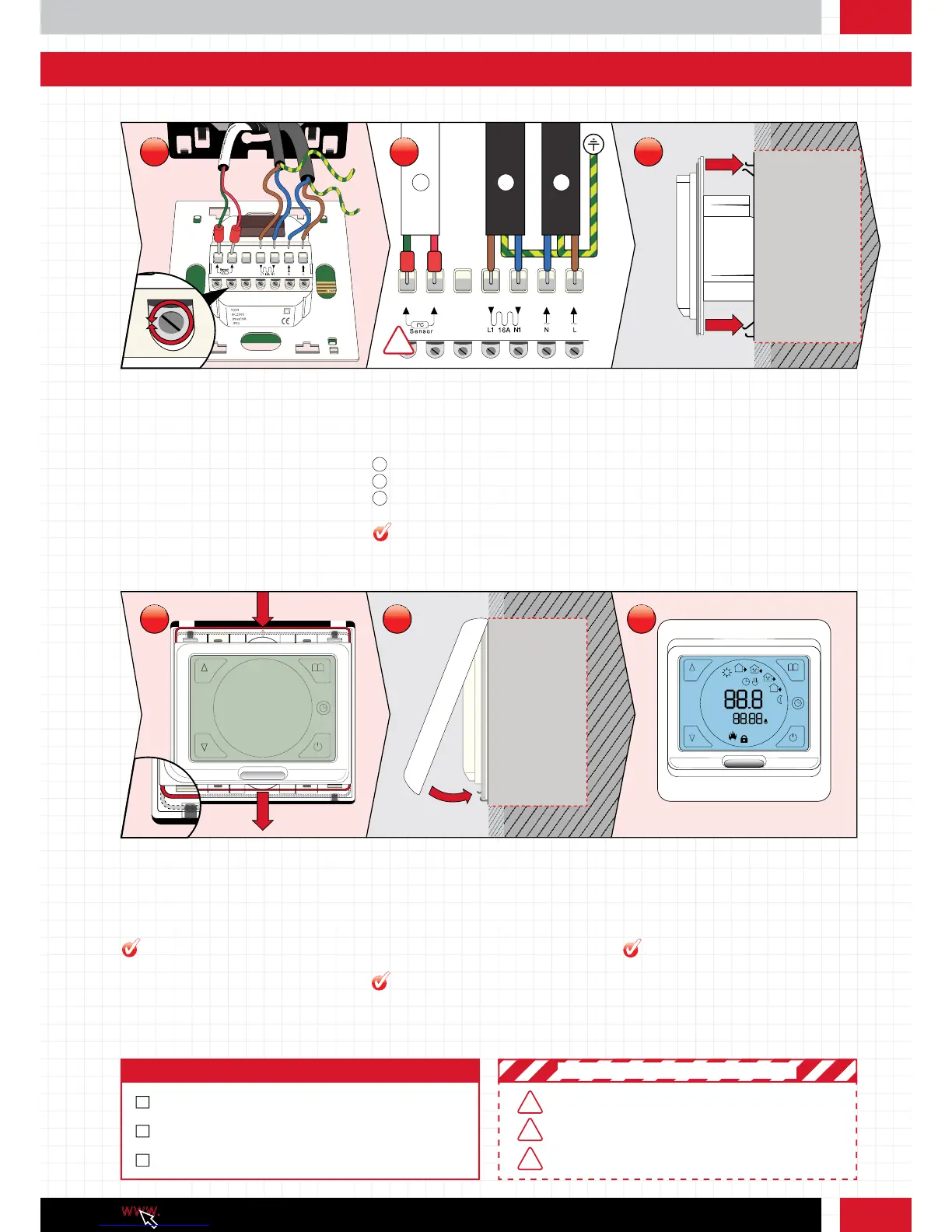
Stage 1: How to install your thermostat
Pull the wires through from your heating
system and expose if required. Loosen the
tension screws to allow the wires to be
inserted and fixed.
Position the cables as shown above and
tighten the tension screws one by one.
Slide the thermostat into position. Ensure the
metal brackets on the black steel wall plate
slide easily back into position.
Step 7: Wiring the Thermostat Step 8: Detailed wiring schematic Step 9: Slide the thermostat into the
back box
!
1
Sensor probe
1
2
Heating cable cold tail
2
3
Power supply
3
1
5
4
3
2
6
7
°C
Gently push the steel wire clip down locking
the thermostat in place.
Clip the face plate into position. To remove the
face plate whilst attached to the wall, gently
use a flat headed screw driver in the notch on
the underside.
Tap the ‘power’ button on the touch screen
and begin to program the thermostat.
Step 10: Clipping the thermostat to
the black steel wall plate
Step 11: Replacing the face plate Step 12: Turn on the thermostat
Use a cable stripper to ensure a good
amount of cable is exposed.
Different coloured fascias are available,
install at this point if you have one.
Ensure circuit is protected by an adequate
RCD unit (5266)
Snubber - If your underfloor heating
system is over 16A you will need to install
a contactor snubber. See the Advanced
Electrical Guide online.
PRO TIP
PRO TIP
PRO TIP
PRO TIP
MAX LOAD 16A
ALL ELECTRICAL WORK MUST COMPLY WITH IEE 17TH EDITION
PART P REGULATIONS
! IMPORTANT SAFETY PRECAUTIONS !
Step 4: Checklist
INSTALL THERMOSTAT AND FACE PLATE
WIRE THERMOSTAT CORRECTLY TO AN RCD
THERMOSTAT POWERS UP
KEEP SENSOR AND THERMOSTAT AWAY FROM HOT OR COLD
EXTERNAL INFLUENCES SUCH AS PIPES
7
10 11 12
8 9