1-29
C2258
C4238
C4239
Disassembly / Repair 137/153
(cont’d)
Solenoid Controlled Auxiliary
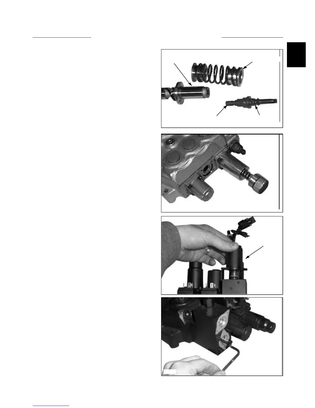
1 Remove the screws retaining the solenoid coil.
Remove the12 VDT solenoid coils. (fig. C4238)
2 Inspected the O ring on the solenoid coils for
damage. Replace if necessary.
3 Remove the screws retaining the solenoid assembly
to the control valve. (fig. C4239). Upon assembly tighten
the screws to 4.9 ft lbs (6.6 Nm).
12 Install the spring return / centering cover and tighten
the mounting screws evenly to 4.9 ft lbs (6.6 Nm). Install
the end cap to the cover and tighten to 7.2 ft lbs (9.8 Nm)
. (fig. C2258)
CONTROL VALVE 1.3
Detent spring and cap
11 Install the spring return / centering cover and tighten
the mounting screws evenly to 4.9 ft lbs (6.6 Nm). Install
the end cap to the cover and tighten to 7.2 ft lbs (9.8 Nm)
. (fig. C2258)
C2238
Spool spring and bushing
Apply Loctite 542
Detent
Detent
Solenoid Coils
Remove Screws