Chapter 1: Connections and Setup
Cable Modem Overview
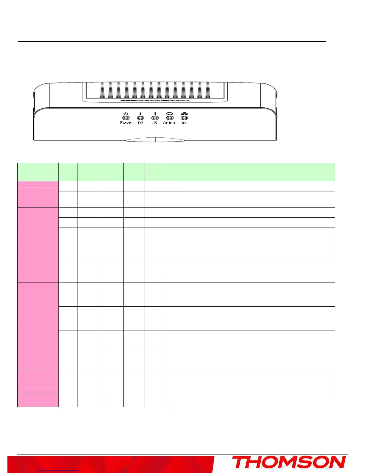
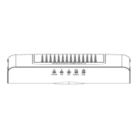
Front Panel
The following illustration shows the front panel of the model:
The LEDs on the front panel are described in the table below (from left to right):
DCM475
TCM470
Power DS US ONLINE
LINK
Description
ON ON ON ON ON Power on 0.25 sec
Boot-up
Operation
X FLASH FLASH FLASH X
Following system initialization complete to (before) DS scanning
ON FLASH OFF OFF X During DS scanning and acquiring SYNC
ON ON FLASH OFF X From SYNC completed, receiving UCD to ranging completed
ON ON ON FLASH X
During DHCP, configuration file download, registration, and
Baseline Privacy initialization
DHCP status, LED SHOULD be ON 1 sec, and OFF 1 sec
TFTP status, LED SHOULD be ON 0.25 sec, and OFF 0.25 sec
ON ON ON ON X Operational (NACO=ON)
DOCSIS
Start-up
Operation
ON FLASH FLASH OFF X Operational (NACO=OFF)
FLASH
FLASH FLASH FLASH FLASH
Wait registration with all DS and all US – Lights Flash
sequentially from the right to left
Minimum duration 3 seconds
X X X X OFF
From 1 to 4 DS, from 1 to 4 LEDs are ON.
From 5 to 8 DS, From 1 to 4 LEDs are flashing
Duration 3 seconds
OFF X X X X From 1 to 4 US, from 1 to 4 LEDs are ON.
Channel
Bonding
Operation
FLASH
FLASH FLASH FLASH FLASH
Wait registration with all DS and all US – Lights Flash
sequentially from the left to right
Minimum duration 3 seconds
CPE
Operation
X X X X
OFF
ON
FLASH
No Ethernet Link
Ethernet Link
TX/RX Ethernet Traffic
SW Download
Operation
ON FLASH FLASH ON X A software download and while updating the FLASH memory
3