HAZARD OF ELECTRICAL SHOCK, EXPLOSION, OR ARC FLASH
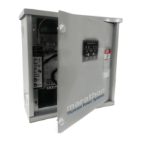
Read and understand this quick start guide before installing and operating the transfer switch
The installer is responsible for compliance with national electrical code requirements with respect to installation of this equipment.
Many components of this equipment operate at line voltage. DO NOT TOUCH. Use only electrically isolated tools.
Install and close all covers before applying power to this equipment
Do not open covers to equipment until ALL power sources are disconnected
This equipment must be installed and serviced only by qualified electrical personnel utilizing safe work practices and appropriate Personal
Protective Equipment (PPE).
Failure to do so may cause personal injury or death
PAGE
A. Introduction ............................................................................................................................... 2
B. Check Equipment Delivery....................................................................................................... 2
C. Check Line Voltage/Amperage ................................................................................................ 2
D. Installation Requirements ........................................................................................................ 2
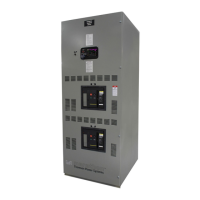
E. Typical Interior Component Layout Drawing ......................................................................... 4
F. Power Conductor Installation .................................................................................................. 5
G. Control Wiring Connections .................................................................................................... 6
H. TSC 9 Controller Configuration Jumpers ............................................................................... 7
I. Equipment Energization Procedure ........................................................................................ 8
a. Pre-Energization Checks .............................................................................................................................................. 8
b. Equipment Energization ............................................................................................................................................... 9
J. Transfer Switch Operation ..................................................................................................... 10
a. Automatic Sequence of Operation ............................................................................................................................. 10
b. TSC 9 Controller Operation Pushbuttons ................................................................................................................... 10
c. ATS Manual Operation ............................................................................................................................................... 11
K. TSC 9 Indication Lights and Pushbuttons ............................................................................ 12
L. BHP Operator Interface Panel (TS 920 Series Transfer Switch Only) ................................ 12
M. Load Shed ............................................................................................................................... 13
N. Schematic Diagram ................................................................................................................ 14