7
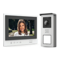
B - PRODUCT DESCRIPTION
9
Indicator light for connecting an additional
monitor :
Red = Connection error
Blue = Connection OK or monitor not present
10
Power supply indicator light
:
Red = Connection error
Blue = Power supply connected correctly
11
Intercom panel connection indicator light
:
Red = Reverse polarity
Blue = Wiring OK
12
Intercom panel connection indicator light
Red = intercom panel not connected (wire
unplugged or cut)*
Blue = connection OK
* This is completely normal if the monitor is
used as an additional monitor on an existing
installation and no intercom panel is directly
connected to it
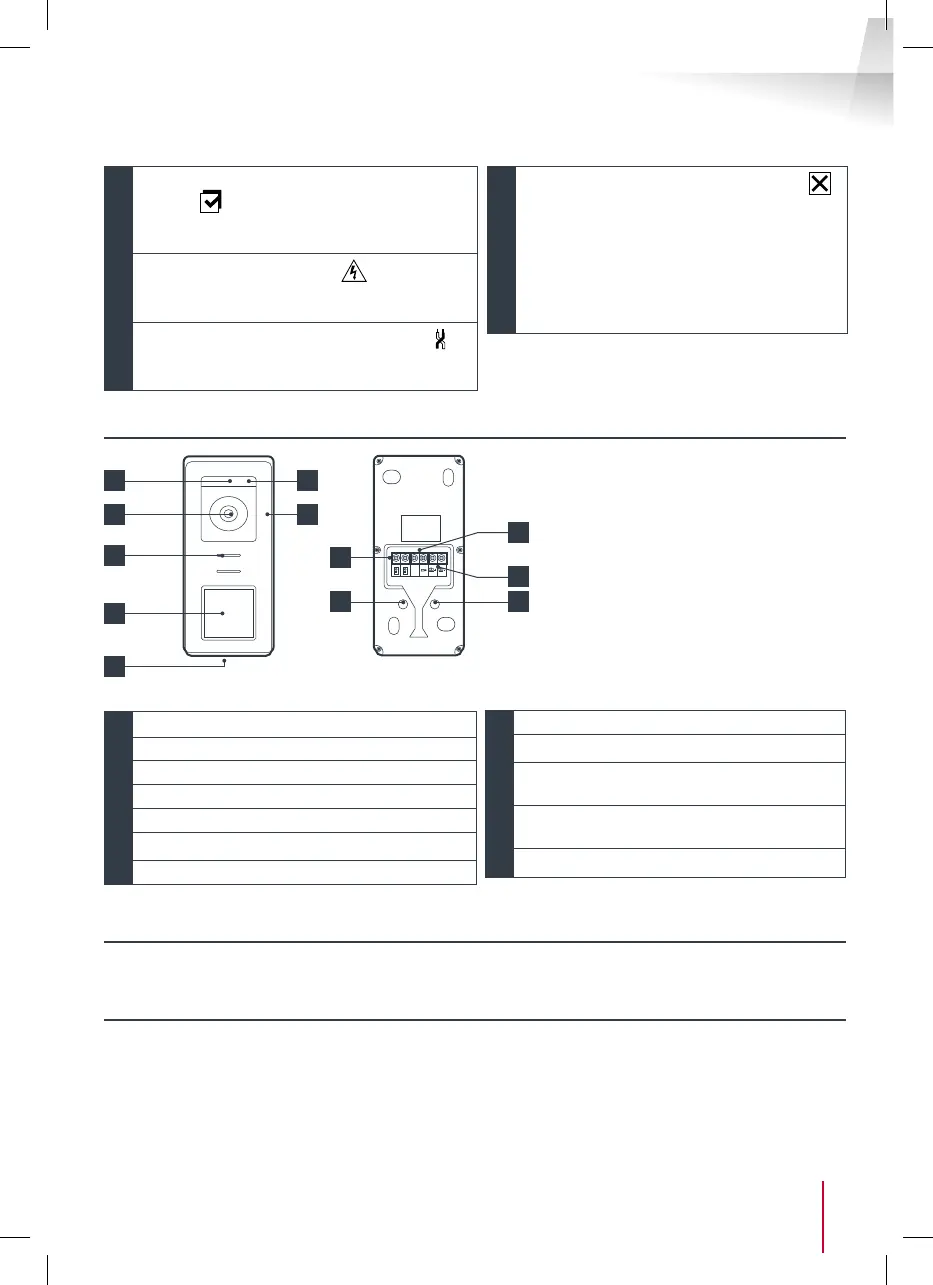
4 - INTERCOM PANEL
1
3 4
8
5
6
7
GND
9
10
1
Twilight sensor
2
White LEDs (night vision)
3
Camera lens
4
Microphone
5
Loudspeaker
6
Backlit call button and RFID badge scan area
7
Tamper-resistant retaining screw
8
Connecting of the monitor
9
Connecting of the electric strike plate
10
Connecting of the dry contact (gate
automation )
11
Loudspeaker volume setting (located under
the rubber button)
12
RFID reset button (under the rubber plug)
5 - WALL BRACKET
The monitor is designed to be xed to the wall. A wall bracket and the necessary fasteners are included.
6 - MAINS ADAPTER
A 230 Vac 50 Hz/15 Vdc 1A mains adapter for powering the monitor is included in the kit. Do not use other
power supplies as they could cause irreparable damage to the device and invalidate the warranty. Do not
cut or extend the wire of the mains adapter or the warranty will be void. The 15V wire of the adapter is
indicated by the presence of a red + 15V label. The ground wire of the adapter is indicated by the presence
of a black ENL label.
Notes:
• When the call button is pressed,
the monitor rings inside and the
video switches on.
• To change the name plate label,
remove the plastic protective
cover on the front by sliding a small
at screwdriver into the notch
provided for this purpose.
11
2
12