Tonarmeinbau
Der Einbau
des
Tonarmes
erfolgt in
umgekehrter Reihen-
folge zum Ausbau.
Beim
Einstecken
des Tonarmes
in
den
Flansch
íst darauf
zu achten,
daB der Tonarm mit
eingeraste-
tem Tonarmrohr,
parallel
zur
AuBenkante
des Chassis
ver-
làuft.
Danach
ist
der Lift
789007'l
zu
montieren
und die Liftbank
7890020
auf der Liftachse
zu befestigen.
Nach
dem Einbau
der Endschalter-Leiterplatte
wird
die
Schaltblende
7886024
auÍgesetzt
und in die
Lichtschranke
eingefr-ih11.
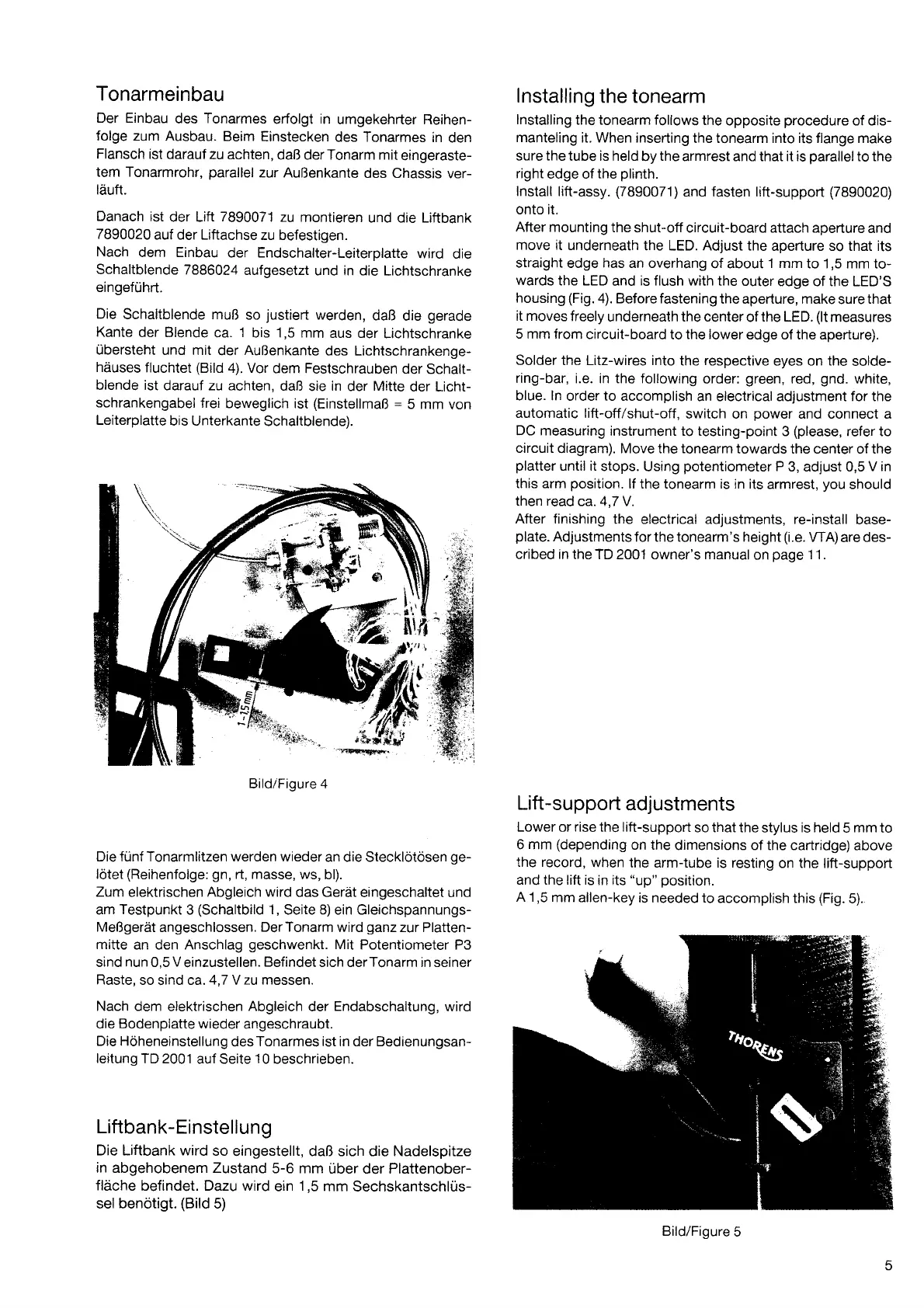
Die
Schaltblende muB
so
justierl
werden,
daB
die
gerade
Kante
der Blende
ca.
1
bis 1,5 mm
aus der
Lichtschranke
rlbersteht
und mit
der
AuBenkante
des Lichtschrankenge-
hàuses
Íluchtet
(Bild
4). Vor
dem Festschrauben
der Schalt-
blende ist
darauf zu achten,
daB
sie
in
der Mitte
der Licht-
schrankengabel
Írei
beweglich ist
(EinstellmaB
:
5 mm
von
Leiterplatte
bis Unterkante
Schaltblende).
Die frlnf Tonarmlitzen werden wieder
an die Stecklötösen
ge-
lötet
(ReihenÍolge: gn,
rt, masse,
ws, bl).
Zum elektrischen
Abgleich
wird das Geràt
eingeschaltet und
am
Testpunkt
3
(Schaltbild
1,
Seite 8) ein Gleichspannungs-
MeBgeràt
angeschlossen.
Der Tonarm
wird
ganz
zur Platten-
mitte
an den Anschlag
geschwenkt.
Mit
Potentiometer P3
sind
nun
0,5
V
einzustellen.
Befindet
sich derTonarm in seiner
Raste,
so
sind
ca.
4,7
Y
zu messen.
Nach dem
elektrischen
Abgleich
der
Endabschaltung,
wird
die Bodenplatte wieder
angeschraubt.
Die Höheneinstellung
des
Tonarmes ist in der Bedienungsan-
leitung
TD 2001
auf Seite
10
beschrieben.
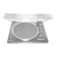
Liftbank-Einstellung
Die Liftbank wird
so
eingestellt, daB sich die Nadelspitze
in abgehobenem Zustand
5-6 mm
uber der Plattenober-
flàche
befindet. Dazu wird
ein
1,5
mm
Sechskantschlus-
selbenötigt.
(Bild
5)
lnstalling
the
tonearm
lnstalling
the tonearm follows
the
opposite
procedure
of dis-
manteling
it. When inserting
the tonearm into its flange make
sure
the
tube is held
by
the
armrest and that it is
parallel
to the
right
edge of the
plinth.
lnstall
lift-assy.
(7890071)
and fasten lift-support
(7890020)
onto it.
After
mounting the
shut-off circuit-board attach aperture
and
move it
underneath
the LED. Adjust the
aperture so that its
straight
edge
has
an overhang
of about
1 mm
to 1,5 mm to-
wards
the LED
and
is flush with
the outer
edge of the LED'S
housing
(Fig.
a). Before fastening
the aperture, make
sure
that
it moves
freely
underneath the center
of
the LED.
(lt
measures
5 mm from
circuit-board
to
the lower
edge of the aperture).
Solder the Litz-wires into
the
respective
eyes on
the
solde-
ring-bar,
i.e. in the following
order:
green,
red,
gnd.
white,
blue. ln
order to accomplish
an electrical adjustment for the
automatic lift-off/shut-off,
switch on
power
and connect a
DC measuring
instrument to testing-point
3
(please,
refer to
circuit
diagram). Move the tonearm
towards the center of the
platter
until it
stops.
Using
potentiometer
P
3, adjust 0,5
V in
this arm
position.
lÍ the tonearm is in its
armrest,
you
should
then
read
ca. 4,7 Y.
After finishing
the electrical adjustments, re-install
base-
plate.
Adjustments
Íor the tonearm's height
(i.e.
WA)
are
des-
cribed
in
the ïD 2001 owner's manual
on
page
1 1 .
Lift
-support
adjustments
Lower or rise the lift-support
so that the
stylus
is held
5
mm
to
6 mm
(depending
on the
dimensions of the
cartridge) above
the record,
when
the arm-tube is resting
on the lift-supporl
and the lift is
in its
"up" position.
A 1,5
mm allen-key
is needed to
accomplish this
(Fig.
5).
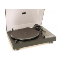
Bild/Figure 4
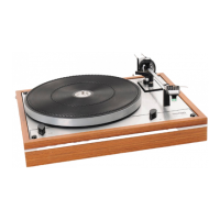
Bild/Figure
5
r